The beginning of a vintage monograph from nearly thirty years ago (Issue No. 05, 1996, of the magazine “Letectví + kosmonautika”).
Convair is a catchy acronym for the rather long name of the American aircraft manufacturer Consolidated Vultee Aircraft Corporation, which was founded in 1943 following the merger of Consolidated and Vultee. This name came into widespread use after the end of World War II in connection with the launch and promotion of new production programs. The abbreviation became so familiar that even the most knowledgeable people overlooked the fact that the Convair trademark was not officially registered until 1954! Despite the abbreviated name’s nine-year period of unofficial status, the aircraft described in this monograph can be classified as a typical “Convair”— —those aircraft that were presented to the public under the Convair designation, even though by the time the trademark was officially registered, the aircraft was already nearing the end of its service life. It is interesting to note that elements of the future XP-92 were actually created on the other side of the Atlantic during World War II on the drawing board of German designer and aerodynamics theorist Dr. Alexander Lippisch.
In August 1945, immediately after the end of World War II, the U.S. Army Air Forces announced a competition to develop a supersonic fighter-interceptor capable of climbing to an altitude of 50,000 feet (15,240 m) in four minutes and reach a maximum speed of 700 miles per hour (1,126 km/h). However, at the time of the competition, neither Convair Corporation nor Dr. Alexander Lippig himself had any idea that the project would be closely linked to German research in the field of high-speed flight and propulsion systems. Convair’s management assigned responsibility for the project to its branch in Downey, California, where a select team of theorists and designers soon assembled. The complexity of the task matched the abilities of the team members, who included such well-known figures as Chief Designer Jack Irwin, Assistant Chief Designer Frank W. Davis (creator of well-known wing airfoils and the wings themselves, such as the Liberator bomber’s wing), Head of Development Adolf Burstein, and Chief Aerodynamicist Ralph H. Schick. Wallace W. Whitty became the project engineer. In late summer 1945, when the project team—which had been given the internal designation Model 7-002—gathered for its first meeting in Downey, Dr. Lippisch traveled from defeated Germany to the United States to work for an extended period at a research center located at Wright Field, an Army Air Forces base in Ohio. The decision to invite Alexander Lippisch to the United States was of great significance, as the results of his work had a long-lasting influence on the design of U.S. Air Force combat aircraft, particularly those manufactured by Convair.
The Model 7-002 program’s select team faced a truly titanic challenge, the successful completion of which could bring the company not only a steady stream of orders but also an extraordinary boost in prestige. However, in the fall of 1945, it was too early to even consider a practically operational design (the speed of sound was first exceeded by the Bell X-1 experimental rocket-powered aircraft only in 1947). There was a lack of experience in aerodynamics, and there was also uncertainty regarding a suitable powerplant. The turbojet engines produced at that time were not yet capable of generating the thrust necessary to provide the airframe with the required performance characteristics. After some initial interest in pure rocket engines—which were ultimately rejected due to the impracticality of their very limited operating time—a unique combination of a direct-flow air-breathing jet engine and a rocket engine was developed in Downey. The operating principle of this powerplant, called an “augmented rocket,” had already been known and tested in practice (albeit on a much smaller scale). It consisted of a ramjet engine running on hydrocarbon fuel and comprising a massive tube that formed the aircraft’s fuselage, combined with a bank of rocket engines located inside the tube, which, during takeoff, provide the ramjet (and consequently the aircraft) with the speed necessary for the ramjet to operate independently. It was assumed that not all of the rocket fuel would be consumed during takeoff, since the rocket engines could be fired in flight to improve performance in combat situations, as well as during the critical low-speed phase of the landing approach.
In the initial design phase of the Model 7-002 aircraft, it was a mid-wing design with a cylindrical fuselage that formed the casing for a direct-flow air-breathing jet engine, with a swept-back wing of short chord length and a V-shaped tail. The cockpit for the reclining pilot was intended to form the central cone of the ramjet’s pressure nozzle. After abandoning the ski-type landing gear attached to the fuselage, engineers at Convair Corporation designed a retractable tricycle landing gear, whose struts were located in the fuselage (nose strut) and at the wing-fuselage junctions (main struts). In the model shop at the Downey plant, technicians built several aircraft models—both for demonstration and for wind tunnel testing. In early 1946, two small models of the aircraft—which differed from one another in their landing gear and minor details of the cockpit and tail assembly—were sent, along with the relevant documentation, to the governing body of the U.S. Army Air Forces: the Army Air Forces Materiel Command at Wright Field, Ohio. Thus, the results of the Downey team’s work and Dr. Lippisch’s knowledge drew closer together, at least “within sight.”
The real connection took place a few days later, when Ralph H. Schick, an aerodynamics specialist at Convair Corporation, arrived at Wright Field from California, where he met Alexander Lippisch. As experts in their fields, the two leading aerodynamicists immediately hit it off—their lively conversations, which were of interest not only to linguists (since Schick spoke a little German), and Lippisch had a fairly good command of English—continued day after day until late in the evening. Alexander Lippisch assessed the Convair engineers’ approach to developing the Model 7-002 and proposed improving the aerodynamics while simultaneously reducing weight by using a delta wing with elevons as control surfaces and eliminating the classic horizontal tail, transforming the aircraft into a tailless plane.
Dr. Lippisch had compelling reasons for making such a proposal. Not only had he completed the design calculations for a tailless aircraft with a triangular wing as early as the second half of the 1930s, but he also conducted practical experiments in the latter half of the war with a piloted, unpowered glider built according to this aerodynamic configuration. Alexander Lippisch also designed tailless combat aircraft, one of which, the Me 163 Komet, went into serial production by Messerschmitt and saw combat, while another, equipped with a Convair ramjet, was under development in 1945 in preparation for the construction of a prototype. Alexander Lippisch brought both of his designs to Wright Field, and the U.S. Army Air Forces even transported the aforementioned unpowered experimental glider from Germany.
Dr. Lippisch began work on a combat aircraft with a delta wing in 1937. It was then that the Reich Aviation Ministry (Reichsluftfahrtministerium – RLM) began work on Projekt X. The plan was to develop a jet fighter-interceptor with high speed and rapid climb rate. Despite many twists and turns, this program was ultimately realized in the form of the Me 163, but before the aircraft was actually built, the development process took various paths. One of these paths was the Lippisch DM 1 airframe (DM stands for Darmstadt and Munich, whose universities were officially involved in its development as a “sports” aircraft). This glider was intended to test the aerodynamic configuration of the Lippisch P 13 fighter, equipped with a direct-flow air-breathing jet engine. Construction of the DM 1 glider began in November 1944. Lippisch’s idea was to combine a wing with a 60° leading-edge sweep with a fuselage that generated lift, thereby combining all the aerodynamic advantages of this design. A distinctive feature of the DM 1 airframe was its massive vertical tail with a glass panel at the leading edge for the pilot’s cockpit located inside. To provide forward visibility, the lower portion of the glider’s nose featured a glass panel through which the pilot could observe the terrain. During flight tests, the glider took to the air while being towed by a twin-engine Siebel Si 204 passenger aircraft. The glider was released at various altitudes (reportedly, the maximum release altitude was 7,900 meters). In a dive, the DM 1 glider reached a speed of 560 km/h, and during the tests, its minimum speed and overall controllability were verified. Allegedly, the DM 1 retained full controllability at a speed of 70 km/h. Testing of the glider was not completed by the end of the war, as the second phase—during which an auxiliary rocket engine was to be installed in the rear of the glider—was never carried out. After being towed by a Si 204 aircraft and released, the glider pilot was to ignite the rocket engine, after which the DM 1 was to accelerate to a speed of 800 km/h in level flight. These would undoubtedly have been impressive performance figures for an all-wood glider built using conventional methods typical of sport gliders. Delivered to Wright Field Air Base, the unpowered DM 1 glider retained its tricycle landing gear with a nose wheel (the glider equipped with a rocket engine was to have this replaced by a spring-loaded ski mounted under the fuselage). After being recommissioned, the DM-1 glider was tested at Wright Field by experts from the Army Air Corps’ Logistics Directorate, NACA (National Advisory Committee for Aeronautics [NACA]; the predecessor of NASA), and Convair. The glider took to the air, towed by a C-47 transport aircraft.
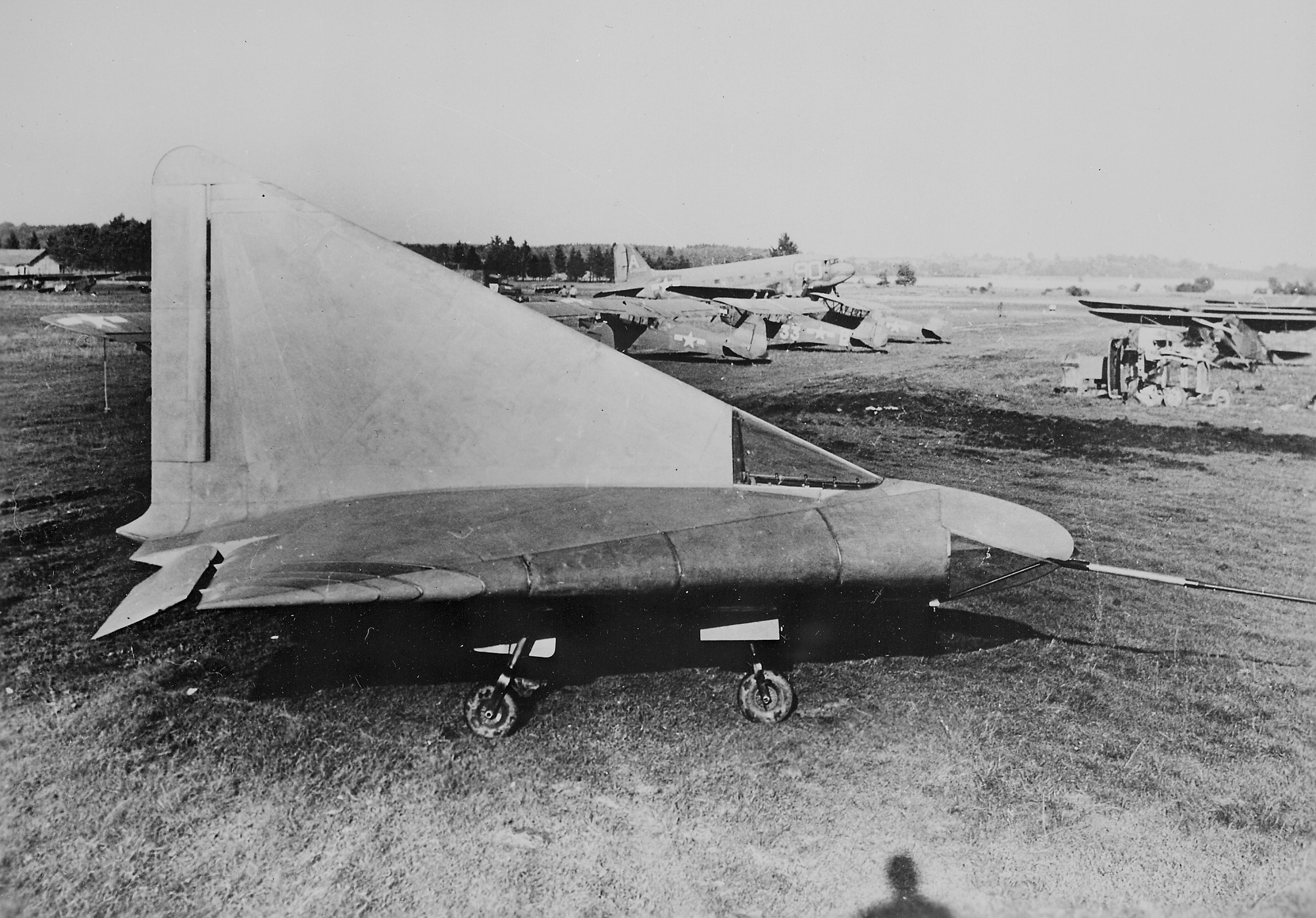
Alexander Lippisch’s experimental DM 1 glider at Wright Field Air Base (wingspan 5.92 meters, length 6.60 meters, wing area 20.00 square meters, takeoff weight 460 kg). Photo: waralbum.ru
The fighter design developed by Dr. Lippisch, designated P 13, retained the basic aerodynamic concept of the DM 1, with the fuselage and wing integrated into a single structure that generated lift. However, the powerplant was to be a specially developed direct-flow air-breathing jet engine, whose primary fuel was to be brown coal dust. The coal dust was to be heated in containers by the flame of compressed lighting gas from special tanks to a temperature at which carbon monoxide is released from it. It was then assumed that the carbon monoxide would combine with atmospheric oxygen in the airflow to form carbon dioxide, increasing in volume and pressure. It was further assumed that the compressed carbon dioxide, as it exited the nozzle, would generate static thrust. A rocket engine was to be installed in the rear of the P-13 fighter for takeoff and acceleration up to a speed of 320 km/h, at which point, according to calculations, the “coal-powered” ramjet was supposed to begin operating. A supply of 800 kg of coal dust was intended to ensure a flight duration of 45 minutes. The design of the P-13 fighter was finalized in the spring of 1945; that same year, production documentation was completed and the powerplant had already undergone testing. The P 13’s parts and assemblies were destroyed by the Germans even before the Americans arrived in Darmstadt. Theoretical calculations, the results of aerodynamic tests, and part of the design documentation—all of this was utilized by Dr. Lippisch during his subsequent work on Convair’s Model 7-002 project.
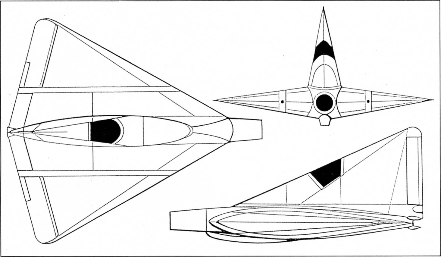
Design drawing of the Lippisch P 13 fighter. The aircraft was to have a wingspan of 5.92 meters, a length of 6.60 meters, a wing area of 20.00 square meters, a takeoff weight of 2,300 kg, and was expected to reach a speed of 1,650 km/h at altitude (a maximum Mach number of 2.5!), with a flight duration of 45 minutes
In May 1946, the U.S. Army Air Forces officially announced that Convair had won the contract for the supersonic fighter-interceptor program, designating the aircraft XP-92. For reasons of secrecy, work on the program was conducted under the code name Project MX-813. Funding for the project was provided under contract W33-038-ac-14547.
Work on finalizing the design of the Model 7-002 project—also known as the XP-92—was in full swing. The very first wind tunnel tests at Valtie Field (with a test section 1.22 meters in diameter) confirmed Dr. Lippisch’s concerns that a highly swept wing combined with a short cylindrical fuselage would exhibit unsuitable performance characteristics at low speeds. Wake separation at the wing tips began even at low angles of attack, and the aircraft’s longitudinal stability was very low. A different wing configuration had to be found. It was at this point that the results of Dr. Lippisch’s work were proposed. In July 1946, development of the new XP-92 fighter design—featuring a delta wing and no horizontal tail—was completed, after which wind tunnel testing resumed. Results from wind tunnel tests of the P 13 model at the NACA wind tunnel at the Langley Memorial Aviation Laboratory were also already available. Although aerodynamicist Shick and Dr. Lippisch frequently consulted on the development of the XP-92, they ultimately disagreed on key issues. The Convair team rejected Alexander Lippisch’s proposal for a thick wing profile and a smooth transition from the wing to the fuselage. There were two reasons for this decision. On the one hand, Schick did not trust the claim that even with a thick airfoil, the critical Mach number could be high enough; on the other hand, there were practical considerations. It was assumed that the high-thrust engine selected by Convair would have a fairly large diameter (over 2 meters), which would not allow for a smooth transition between the wing and the fuselage.
The XP-92 was designed with a relatively thin triangular wing having a relative thickness of 6.5% and a leading-edge sweep of 60°. The trailing edge was occupied by ailerons that were aerodynamically compensated and weight-balanced. The wing design utilized the nearly symmetrical 651-006.5 airfoil developed by NAKA.
The XP-92’s power plant was to be a gasoline-fueled direct-flow air-breathing jet engine. The ramjet’s thrust was to be provided by a bank of sixteen internal rocket engines (powered by gasoline and liquid oxygen as an oxidizer), each producing 0.27 kN (27.5 kgf) of thrust. At the same time, it was assumed that these rocket engines would be used to ignite the fuel for the ramjet itself. The aircraft’s initial velocity was to be provided by an additional array of eight rocket engines, which were also to be located inside the ramjet casing and use alcohol as fuel and liquid oxygen as an oxidizer. A thrust of 6.7 kN (683 kgf) was theoretically intended to provide takeoff and acceleration up to a speed of M = 1.65, at which the ramjet would develop maximum thrust. With the ramjet, the XP-92 could remain at an altitude of approximately 15,000 meters for 5.4 minutes and reach a speed of 1,875 km/h (M = 1.75). Even from this brief description, it is clear that the XP-92 fighter’s powerplant was complex to maintain and demanding to operate.
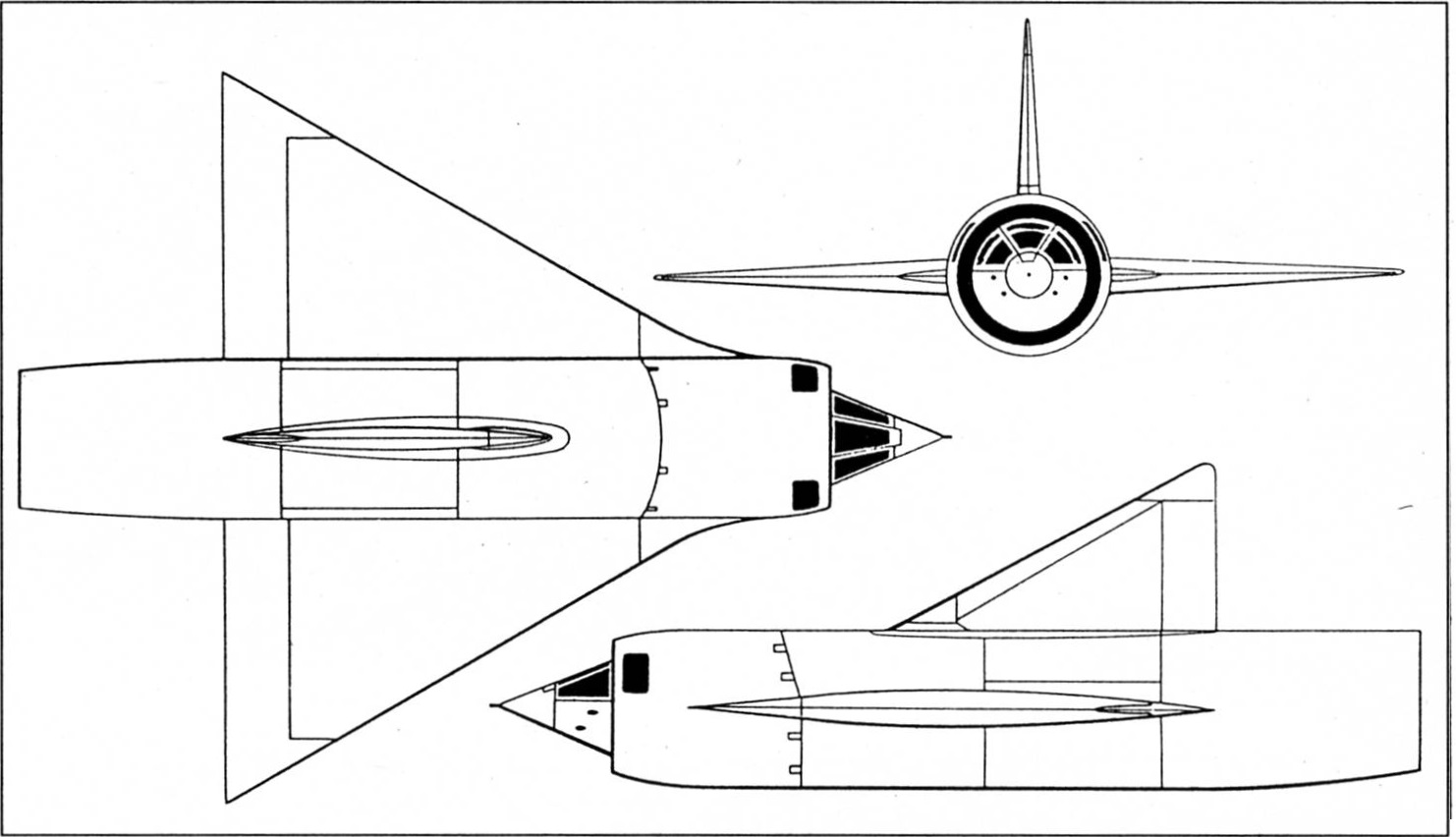
Design drawing of the XP-92 fighter jet. It was to have a wingspan of 9.56 meters, a length of 11.60 meters, and a wing area of 39.50 square meters
The U.S. Army Air Forces planned to use the XP-92 as a missile-armed interceptor for point-defense air defense. In other words, the Army Air Forces wanted a complex aircraft to perform relatively simple tasks. The aircraft was supposed to have retractable landing gear, but it was intended solely for landing! The XP-92, with its landing gear retracted, was to take off while mounted on an eight-wheeled trailer. This trailer was to be equipped with fuel and oxidizer tanks connected to the XP-92’s fuel system to supply the aircraft’s rocket engines. The fuel in the trolley was intended to be used during takeoff (to conserve fuel on the aircraft), and the fuel lines were to automatically disconnect upon separation from the trolley. To further complicate the fuel system, tanks containing fuel and oxidizer for the rocket engines—which would lift the aircraft to combat altitude—were to be suspended beneath the wing pylons. Since the additional tanks were not designed as conventional “disposable” external fuel tanks, they were intended to be lowered to the ground by parachute for reuse.
However, the problems faced by the developers at Convair did not end there. Although the U.S. Army Air Forces planned to arm the interceptor with a pair of guided missiles, their development had not yet been very successful. For this reason, it became necessary to install four 20-mm M-23 cannons as well. In addition, when developing the XP-92, the designers used the calculated two-meter diameter of the ramjet engine and fuselage to redesign the cockpit so that the pilot no longer sat in a reclined position, but sat in a conventional seat, controlling the aircraft with a control stick and pedals. Despite this change, the cockpit fit comfortably within the central cone of the ramjet’s pressure nozzle. To improve side visibility, portions of the pressure nozzle walls were glazed. Then the Convair design team introduced yet another complication to the aircraft’s design —the entire front section of the fuselage, including the cockpit, was designed to separate in an emergency so that the pilot could then exit the “capsule” at a reasonable altitude and descend to the ground using a parachute. The design of the XP-92 cockpit did not allow for the installation of a standard ejection seat, the successful and safe use of which at altitudes above 8,000 meters was still in doubt at that time.
However, Convair’s research capabilities proved insufficient to carry out such a complex program, so NACA (the Ames Aeronautical Laboratory), the California Institute of Technology, and other organizations gradually became involved in the development. At the rocket range located on Wallops Island, NACA launched model aircraft, which were then monitored via telemetry during free flight.
In the early months of 1948, Convair Corporation built a full-scale mockup of the XP-92 fighter. Meanwhile, in 1947, some fairly significant administrative changes took place. The U.S. Army Air Corps was separated from the Army and became a separate branch of the armed forces—the U.S. Air Force. The change in the Air Force’s status also led to changes in the designations of certain categories of aircraft. For example, the designation for fighters was changed from P (Pursuit) to F (Fighter), but no change was made for the XP-92, and the old designation remained in use until the program was terminated.
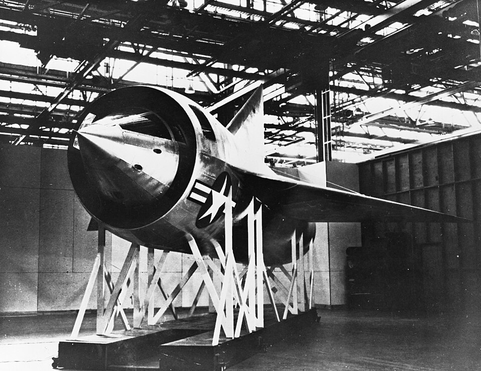
A photograph of an unfinished, full-scale wooden mockup of the XP-92 fighter jet project. Photo from en.wikipedia.org
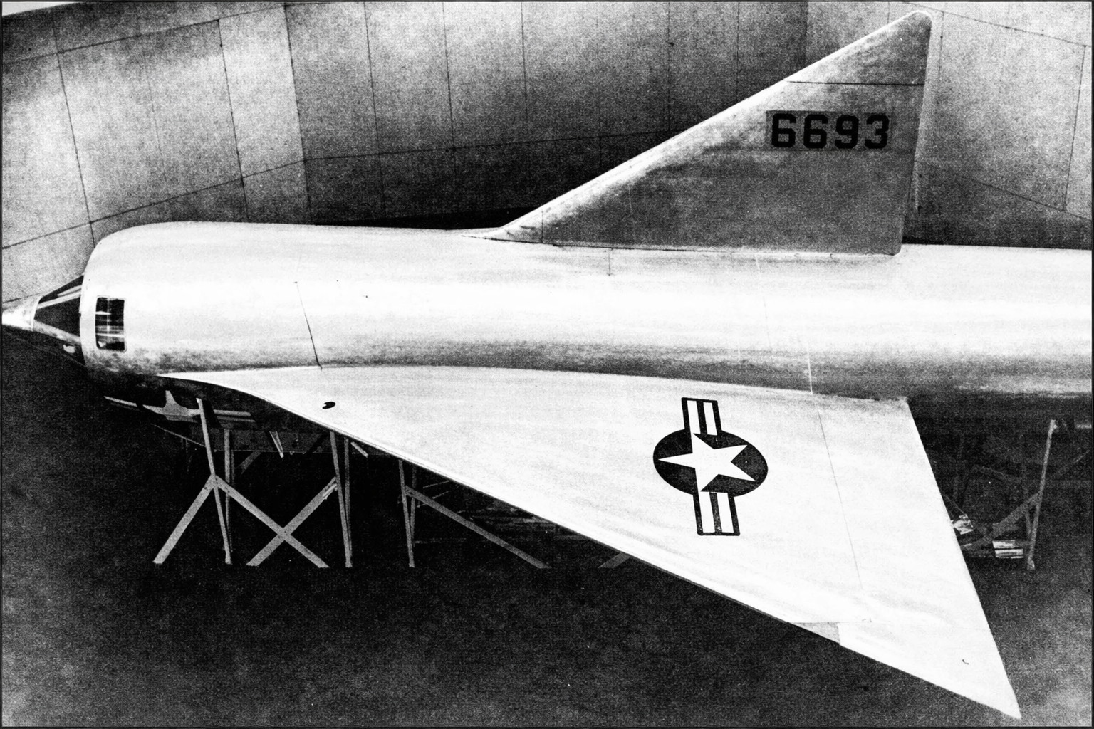
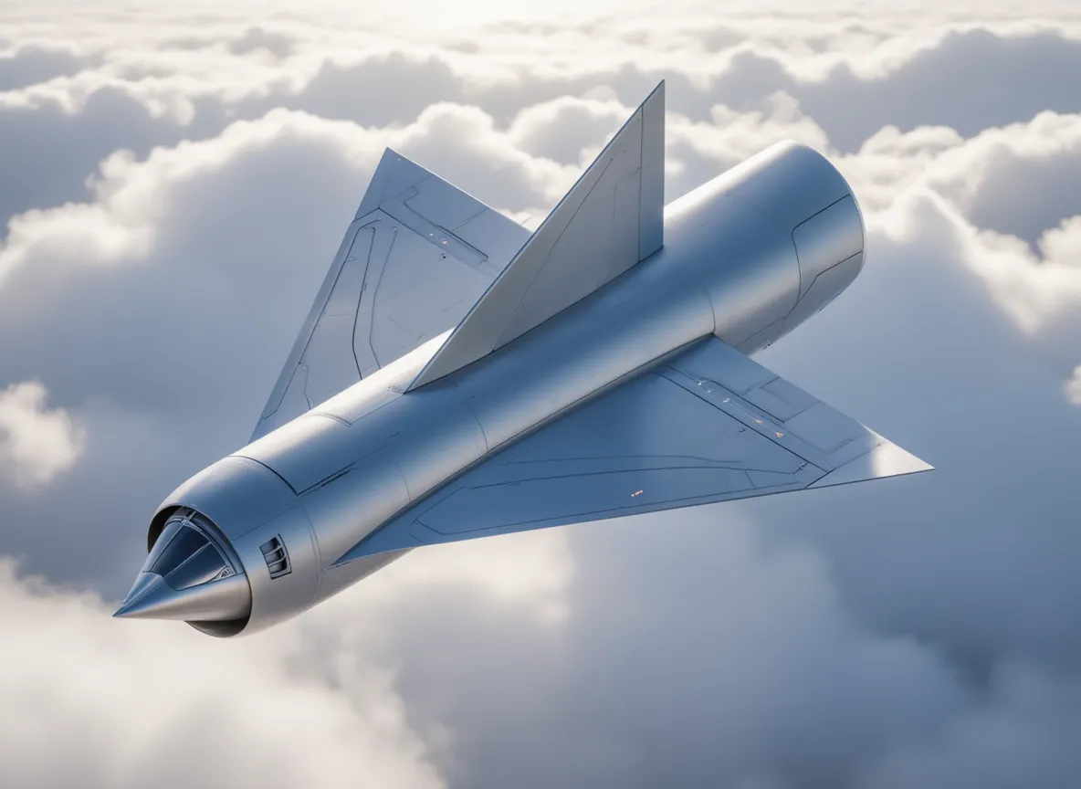
A full-scale model of the XP-92 fighter jet. Image processed by lmarena.ai
As usual, a full-scale mockup of the XP-92 was inspected by specialists from the U.S. Air Force Logistics Command. The power plant and the aircraft control system, featuring 100-percent irreversible booster control (with hydraulic actuation), remained controversial technical choices in the project. Chief Project Engineer Wallace W. Whitty had to answer countless tricky questions. When the U.S. Air Force commission realized the complexity of the project and identified the necessary challenges regarding the aircraft’s operational use, it proposed postponing the program’s implementation.
This happened in May 1948. However, for Convair and the U.S. Air Force, the XP-92 program—which was definitively canceled in June of that same year—did not represent money down the drain, as the development work and various tests yielded very valuable results. It was decided to use the XP-92’s main technical components, with the exception of the powerplant, to build a “flying mockup” of a future fighter-interceptor, whose much more realistic performance specifications had been preliminarily published by the U.S. Air Force as early as 1946. The new model, codenamed the 1954 Interceptor, was intended to become the standard fighter-interceptor for the U.S. air defense system. In 1948, the U.S. Air Force assigned the designation F-102 to this aircraft, and it was only logical that its development was entrusted to Convair Corporation. However, before beginning its development, the company had to build an experimental aircraft based on the XP-92 project, equipped with the jet engine available at the time and capable of simulating the flight characteristics of the future F-102 as accurately as possible. For the new variant of the Model 7-002 project, the U.S. Air Force took advantage of changes in the designation system and assigned it the designation XF-92; not least, this was done to avoid funding issues that the U.S. Congress might have raised. For a short time, the design team in Downey was effectively working on two aircraft types—the XP-92 and the XF-92. Much of the work was carried out in parallel, but the new XF-92 program was marked from the outset by the need to save funds that had previously been lavishly spent on countless complex experiments related to the earlier model. However, work on the XF-92 continued at a fairly rapid pace, so that by the time engineers were working on a full-scale wooden mockup of the XP-92, the construction of the XF-92 “flying mockup” was proceeding without any problems.
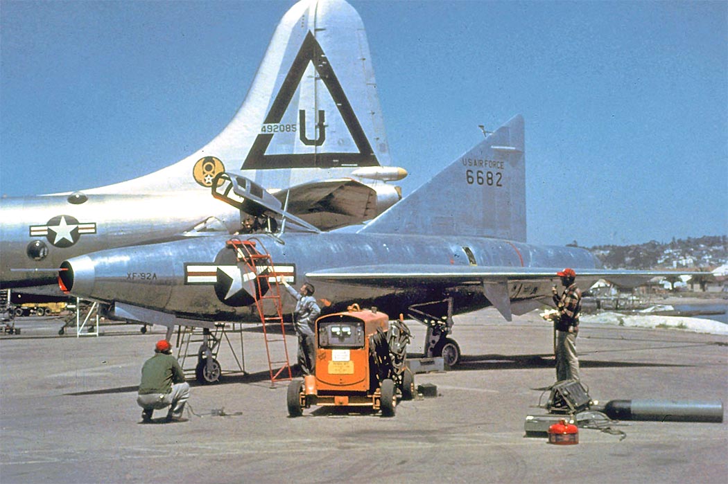
The XF-92 prototype in its original form at the factory airfield in San Diego. In the background stands the massive vertical stabilizer of the Convair B-36 heavy bomber. Photo: airwar.ru
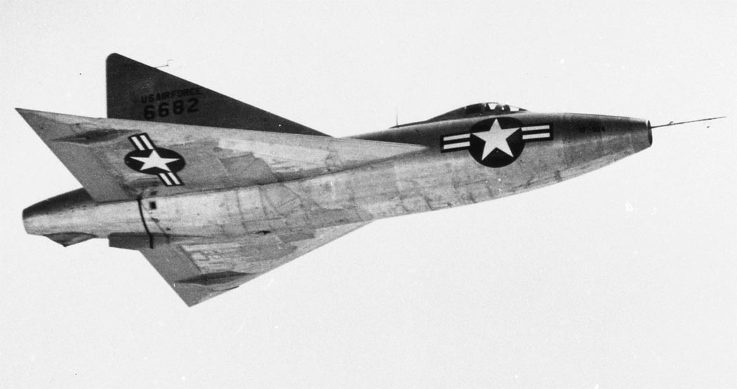
The «metal» XF-92 on its maiden flight. The aircraft is shown in its original configuration, without an afterburner. Photo: airwar.ru
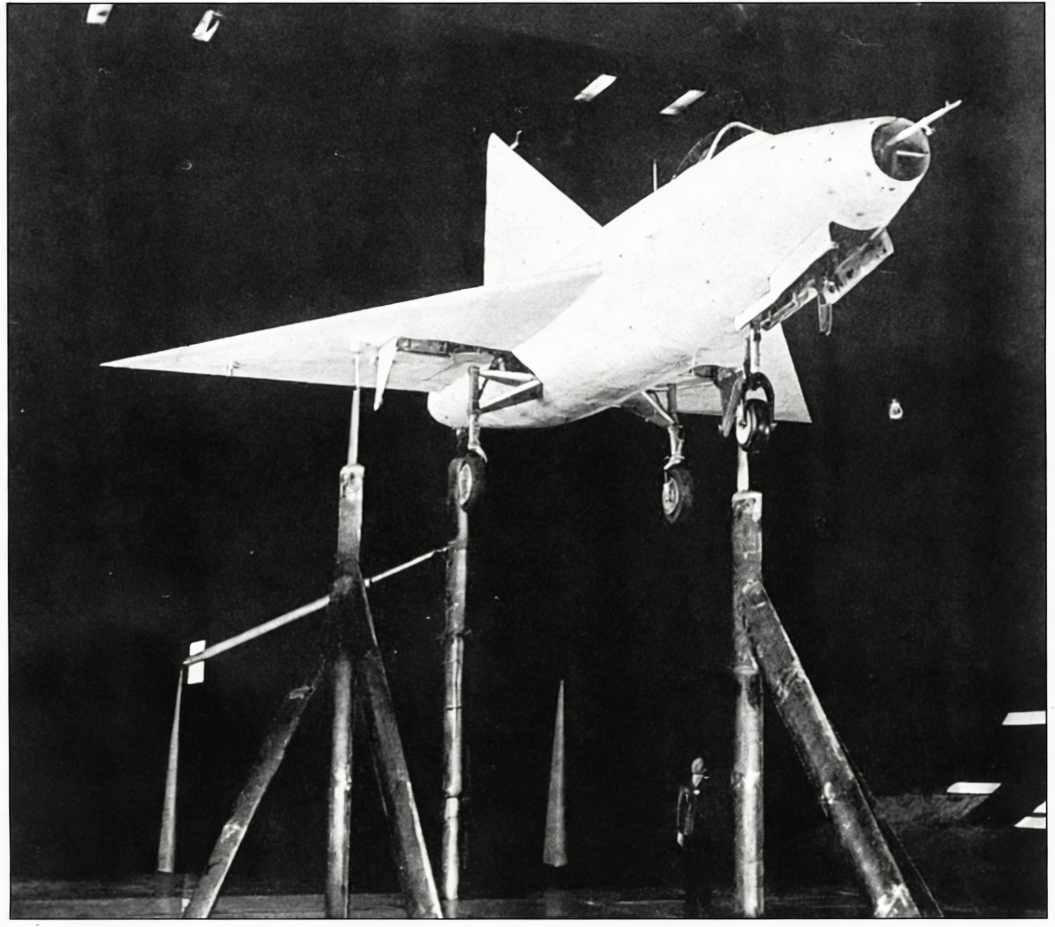
The XF-92 prototype, painted in a contrasting white color, is installed in the wind tunnel at the Ames Aeronautical Research Laboratory, NACA. Image processed by lmarena.ai
Unless otherwise noted, photos are from Convair, AEQ, and the author’s collection. Schematics, drawings, and illustrations are from AEQ and the author’s collection.
Source: Miroslav Balous, “Convair XF-92, Part I,” *Aviation + Astronautics*, May 1996, pp. 40–43/296–299
This translation was first published at – https://vk.com/@710541705-letauschii-treugolnik-convair-xf-92-01