An article by Alexander Chechin from the MODELIST-CONSTRUCTOR website, dated November 11, 2019.
In the late 1920s, the American company Curtiss, known for its flying boats, developed an entire family of Hawk fighters for the U.S. Navy and Marine Corps. These were classic biplanes designed to operate from coastal bases and aircraft carriers, but the military’s desire to expand their combat capabilities led to the development of a float-equipped variant of the fighter. In this new configuration, the aircraft proved itself exceptionally well, and the history of this aircraft became a striking example of the successful conversion of a land-based fighter into a seaplane. This success was no accident—it was based on the use of the latest technologies of the time, the search for and development of which had been the focus of the company’s entire operations since 1917.
The first step toward mastering new technologies was the signing of contracts for the licensed production of modern French and British aircraft, which called for the mass production of 2,000 two-seat British F.2B fighters, 1,000 S.E.5 fighters, and 3,000 French SPAD XIII fighters. Not everything went according to plan. For example, only 26 F.2Bs were produced because the U.S. government required that the 250 l.s. “Eagle” engines with new American “Liberty” engines rated at 400 l.s., but Bristol considered such a replacement unacceptable and, after several accidents, terminated its contract with Curtiss. The contract to manufacture the French fighters was canceled before assembly of the first aircraft began, and only the S.E.5 was produced in the planned quantity.
In the years that followed, the Kertiss factories also built aircraft for American companies—the “Orenko D” fighters and the MB2/NBS-1 bombers manufactured by Martin.
In early 1918, the U.S. government, wishing to equip its forces with aircraft of its own design, began awarding contracts for their design and production on a competitive basis. The first Curtiss aircraft developed for the competition was the Model 18-T “Wasp” triplane (originally designated “Model 15”). This two-seat fighter had the most powerful powerplant of its time, featuring a 400-l.s. “Curtiss-Kirham” K-12 engine rated at 400 l.s., and was considered the fastest military aircraft in the world for some time (at full load, it reached a speed of 264 km/h). By the end of the war, development of the two “Wasp” prototypes had been completed, but due to their high speed, the Navy used the 18-T only as racing aircraft.
«Curtiss» participated in yet another government program. The Army Air Corps Design Branch developed a new night fighter, the PN-1. The company won a contract to build two prototypes. But they turned out to be exceptionally unsuccessful; only one was built, and even that one did not fly. However, Curtiss engineers did develop a technology for manufacturing a welded tubular fuselage.
Curtiss then created true masterpieces of sports aviation—the R2C-1 aircraft—by using the D-12 and D-12A engines, which were new variants of the K-12 engine. Their design incorporated 18-T technology, specifically a multilayer wooden semi-monocoque fuselage. Between 1921 and 1925, the R2C set several world speed records. However, in official Navy documents, they were listed as experimental fighters, since the U.S. Congress prohibited the Navy from funding the development of racing aircraft in the postwar period.
The first production Curtiss TS1 fighter was introduced in 1922. The aircraft itself was developed by the Naval Air Bureau (BuAer). The order was very modest—only 34 aircraft. The first five were built at the Naval Air Plant in Philadelphia. The underpowered engine (200 l.s.) prevented the company from incorporating new technologies into the design. Therefore, Curtiss proposed redesigning the aircraft to turn it into a modern fighter. In 1924, the Navy gave its approval, signing a contract for the construction of two such aircraft and designating them as the F4C-1.
The next Navy fighter from Curtiss was a copy of the Army’s P-1 Hawk. It was produced under the designation F6C-1. As for the name “Hawk,” it—like all other bird-themed names for Curtiss aircraft—was considered unofficial. The company began giving names to its aircraft in 1919. Even if the military did not use the company’s name for the aircraft, Curtiss included it in advertisements and on various documents.
The reason the P-1 entered service with the Navy was its powerful, water-cooled D-12 engine. The Navy’s first order called for the delivery of nine F6C-1s. They differed from the Army versions only in their paint scheme.
The aircraft’s fuselage frame was welded from steel tubes. The ailerons, keel, and rudder and elevator had aluminum structural components. The trapezoidal wings, featuring the new Clark Y airfoil—a hallmark of Curtiss aircraft—were connected by N-shaped profiled struts, forming a sturdy biplane box structure. Fuel was stored in a single fuselage tank with a capacity of 570 liters, but an additional 190-liter flat-topped tank could be suspended beneath the fuselage. The aircraft was armed with two 7.62 mm Browning synchronized machine guns.
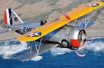
Deliveries of the F6C-1 to the Navy began in September 1925. The first one, with the tail number A-6968, was assigned to the Anacosta Air Station in Virginia, where it underwent comprehensive testing on behalf of the Marine Corps. The next two were tested on two floats and were equipped with a new metal propeller patented by Curtiss, which was used in later modifications. The wooden single-rib floats were mounted on profiled metal struts attached to the wheeled landing gear suspension points. The tail skid was not removed from the floatplane, yet the fighter steered steadily across the water and took off easily. Formally, all F6C-1s were assigned to VF-2 Squadron in San Diego, California.
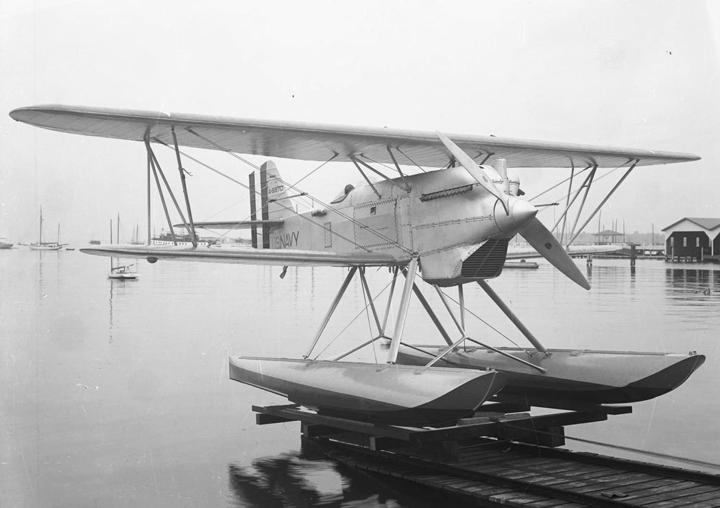
F6C-1 float-equipped seaplane fighter. Photo: airwar.ru
The last four aircraft ordered were designated F6C-2—a variant with reinforced landing gear and a modified tail skid for operation from aircraft carriers.
In 1926, F6Cs from VF-2 were used in experiments involving dive bombing. At an altitude of 760 m, the aircraft was put into a 45° dive, and the bomb was dropped at an altitude of 120 m. The tests were successful. And on May 14, 1926, a seaplane from VF-2 with tail number A-6970 won the U.S. Marine Corps Prize Race, reaching a speed of 212 km/h.
The F6C-1 fighters remained in service with the Navy until February 1931, logging an average of 500 flight hours. As these figures show, they were not used very intensively, which cannot be said of the F6C-3 aircraft.
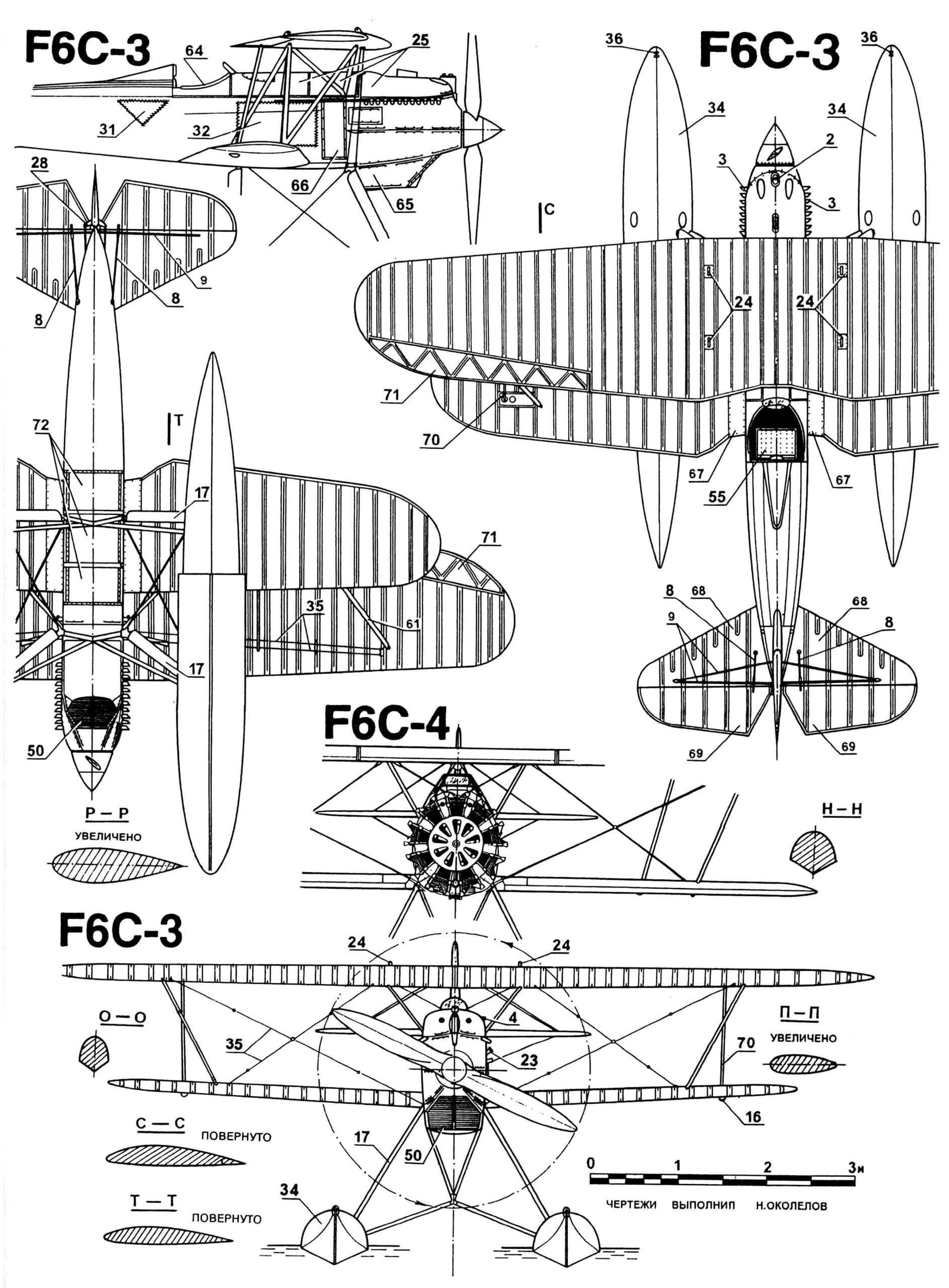
F6C Hawk Seaplane Fighter: 1 — propeller spinner; 2 — water tank; 3 — exhaust pipes; 4 — oil tank filler neck; 5 — machine gun access hatch; 6 — nose cone; 7 — rear cockpit hatch, hinged; 8 — elevator control rods; 9 — stabilizer struts; 10 — rudder; 11 — elevator rockers; 12, 30 — hinged access hatches to the control system; 13 — landing gear strut; 14 — hatch latches; 15 — footrest; 16 — aileron rocker fairing; 17 — float struts; 18 — engine start handle; 19 — opening for the engine start handle; 20 — engine panels, removable; 21 — fixed-pitch propeller, steel; 22 — machine gun port; 23 — fuel tank filler neck; 24 — lifting eyes for crane handling; 25, 32, 60, 66, 72 — service hatches; 26 — cockpit canopy; 27 — rudder suspension assemblies; 28 — rudder rocker arm; 29 — rudder linkage; 31 — access hatches to the rear cabin compartment; 33 — float strut braces; 34 — float; 35 — wing struts, ribbon-type; 36 — mooring rings; 37 — rudder assembly, power-operated; 38 — keel assembly, power-operated; 39 — radiator shutters control lever; 40 — engine control lever; 41 — elevator and aileron control stick; 42 — instrument panel; 43 — machine gun; 44 — ammunition box; 45 — upper wing rib; 46 — oil tank; 47 — Curtiss D-12C engine; 48 — machine gun extension tube; 49 — engine mount; 50 — radiator shutters; 51 — radiator; 52 — fuel tank; 53 — control pedals; 54 — lower wing rib; 55 — pilot’s seat; 56 — tool bag and emergency supplies; 57 — fuselage structural kit; 58 — fuselage struts; 59 — Pratt & Whitney R1314 “Wasp” engine; 61 — wing struts; 62, 65 — removable radiator panels; 63 — float stiffener; 64 — soft cockpit side panel covering; 67 — reinforcing strips; 68 — stabilizer blades; 69 — elevators; 70 — aileron linkage; 71 — aileron
The third variant resulted from the modification of the F6C-2 to the Army’s R-1A standard. These aircraft featured a fuselage extended by 75 mm and new D-12C liquid-cooled engines. On some aircraft, the 7.62-mm right-side machine gun was replaced with a 12.7-mm machine gun. This armament was intended to become standard for the U.S. Navy’s biplane fighters. The new “Hawks” could also carry bombs in place of the under-fuselage fuel tank, which was suspended between the landing gear struts.
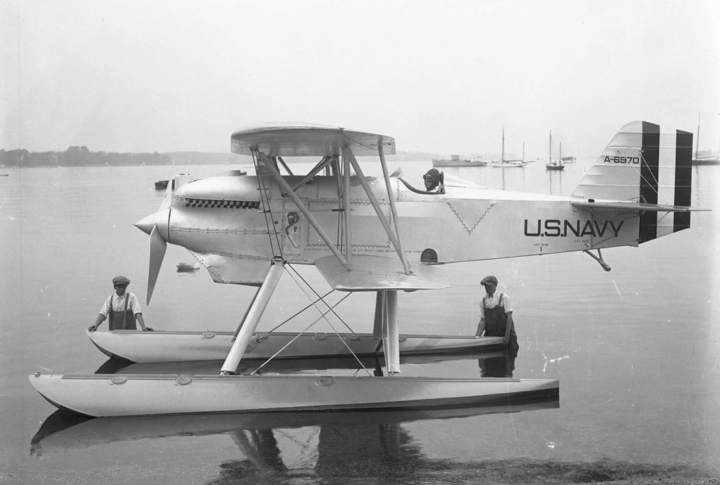
F6C-1 floatplane fighter, later converted to the F6C-3. Photo courtesy of airwar.ru
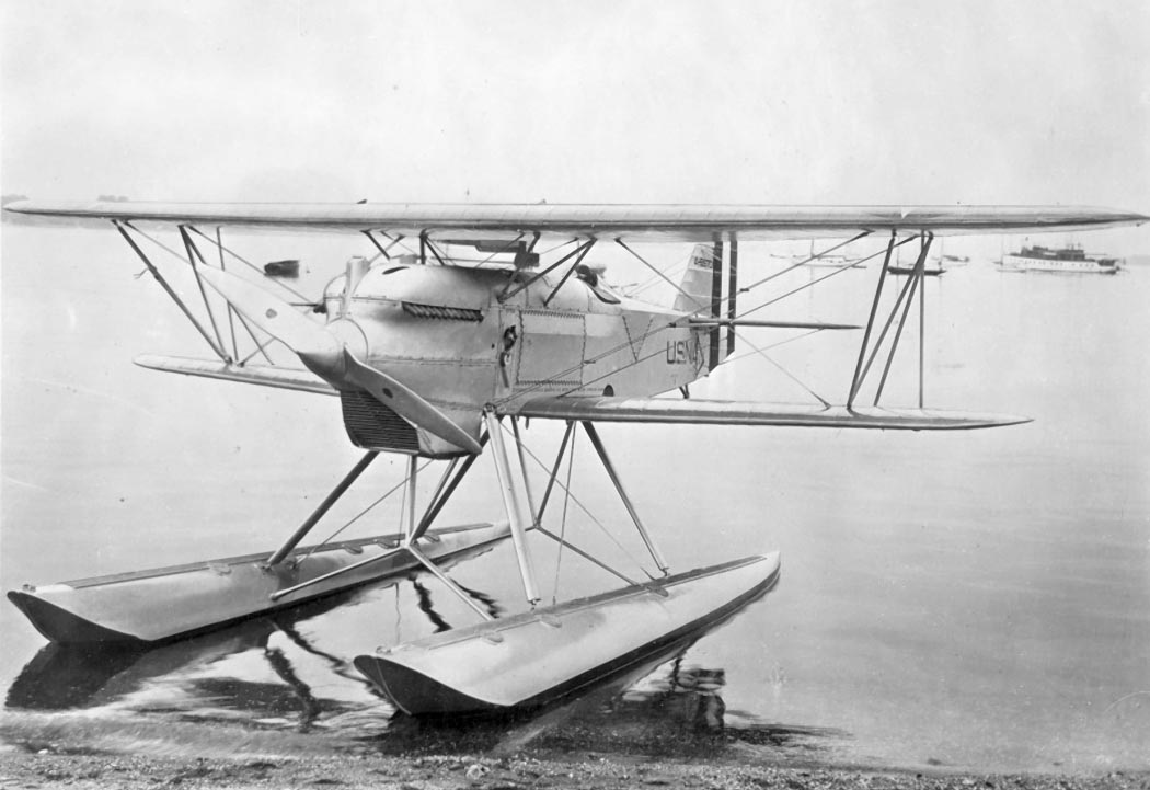
F6C-1 floatplane fighter, later converted to the F6C-3. Photo courtesy of airwar.ru
Deliveries of production-model F6C-3s began in October 1926. The first 18 aircraft were assigned to Squadron VF-5 at the Norfolk, Virginia, base. Some time later, they were transferred aboard the new aircraft carrier USS Lexington (CV-2) and even participated in its ceremonial commissioning into the fleet. This squadron was nicknamed the “Red Rippers,” a name it has retained to this day, even as it has transitioned to different aircraft. Operating the F6C-3s from an aircraft carrier revealed their tendency to yaw to the right when moving across the deck. Consequently, in July 1928, all the aircraft were placed in storage, and the squadron was reclassified as a bomber squadron with the new designation VB-1B. Notably, however, the aircraft were not decommissioned from the ship. This strange “partnership” lasted about a year. Then the Navy decided to use only air-cooled aircraft in its carrier-based aviation. Consequently, all F6C-3s were gradually transferred to the Marine Corps. In June 1932, the last one was decommissioned and brought ashore, with 1,037 flight hours logged.
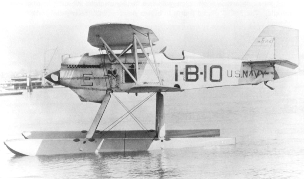
F6C-3 floatplane fighter. Photo courtesy of airwar.ru
The F6C-3s began arriving in the Marine Corps in 1927. They were first used to re-equip Squadron VF-8M, and then VF-9M. Both units were based at Quantico, Virginia. The fighters caused a great deal of trouble for maintenance crews due to wear on the tail strut, and they were typically operated on floats rather than wheels. Between 1926 and 1930, some of them were used as race cars.
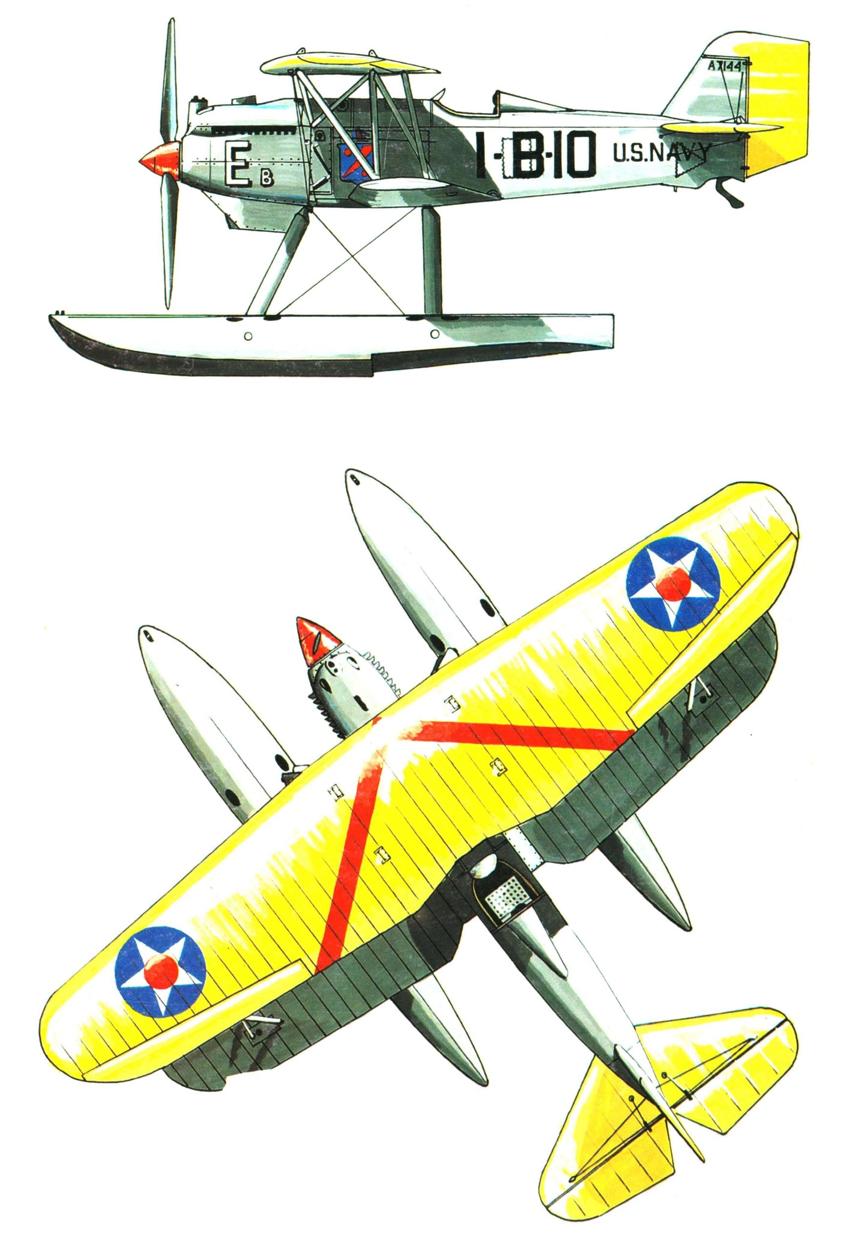
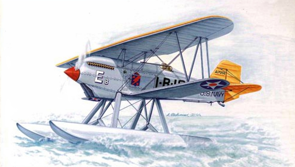
Color scheme of the F6C-3 floatplane fighter. Photo courtesy of airwar.ru
For example, on November 13, 1926, the aircraft with tail number A-7128 participated in the Schneider Trophy race as a reserve. Since the United States had won the cup in 1925, the 1926 race was held in Norfolk. To increase the maximum speed, the engine was tuned to 507 l.s., and the capacity of the under-fuselage fuel tank was increased so that the aircraft could fly 345 qualifying kilometers at maximum engine RPM. The fighter finished fourth with a speed of 222 km/h.
Less well-known were the Marine Corps Cup competitions, established by Glenn Curtiss in 1913. They were held annually for Navy aircraft. F6C-3 fighters competed in them starting in 1926 and won twice (in 1928 and 1930), recording speeds of 255.3 and 266.9 km/h, respectively. The 1930 victory is particularly noteworthy, as it was achieved by an aircraft designed nearly six years earlier—a fact that vividly illustrated the stagnation observed in the development of naval aviation during those years.
Kurtiss’s response to the Navy’s refusal to use water-cooled engines was another modification—the F6C-4. Satisfied with the F6C’s advantages over aircraft from other manufacturers, the Navy itself initiated the modernization and returned one F6C-1 to the company to have a new R1314 air-cooled radial engine “Wasp” from Pratt & Whitney. The nine-cylinder engine produced 420 l.s. Flight tests of the upgraded F6C-1 began in August 1926. Following their successful completion, an order was placed for 31 aircraft. The first aircraft in this series was assembled in March 1927, and serial deliveries began in August. The installation of the new engine reduced the aircraft’s weight by 79 kg. The practical ceiling was 6,961 m, and the speed reached 251 km/h.
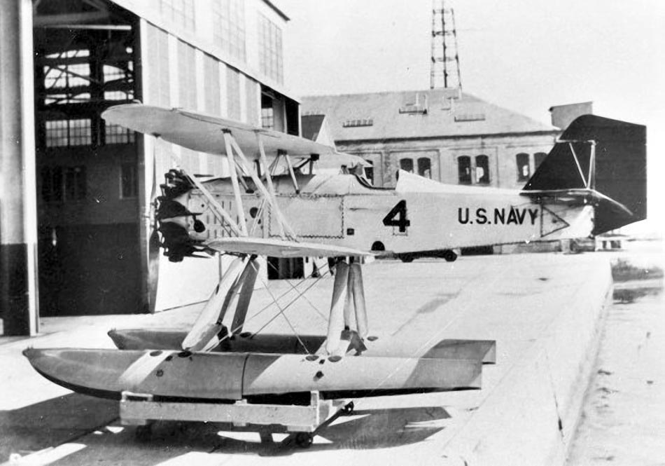
F6C-4 floatplane fighter. Photo from airwar.ru
At the same time as Curtiss, Boeing was developing a new powerplant for its F2B-1 fighter, the first prototype of which took off in November 1926. The Navy ordered 32 aircraft from Boeing.
The first production F6C-4s were assigned to Marine Corps squadrons VF-1M, VF-9M, and VF-10M, and in 1930 in 1930 as part of Squadron VF-2B (eight F6C-4s and eight F2B-1s). Once again, the Curtiss fighters were “refitted” with floats and transferred to the Marine Corps that same year. They remained in service there until 1932. In 1930, the engine cylinders on some F6C-4s were covered with Townend rings. The rings were inexpensive and easy to install, but they failed to deliver the expected increase in speed at the next seaplane races, which puzzled NACA experts. It later became clear that the problem was caused by harmful airflow interference between the rings and the pilot’s canopy. In 1933, the “Hawks” were decommissioned from the fleet as worn out, with a maximum flight time of 1,149 hours. In the late 1920s, several of these aircraft were stationed at Anacosta Air Base to test the new “Hornet” and “Twin Wasp” engines manufactured by Pratt & Whitney.
The F6C-3 Hawk seaplane was a single-engine, single-seat, float-equipped biplane fighter. The truss-frame fuselage was manufactured as a single unit. The transverse structural framework consisted of frames bent from steel tubes; the longitudinal framework consisted of steel tubular stringers. To give the entire structure greater rigidity, the frames were braced together with steel struts. The engine mount was attached to the first structural frame. The fuselage skin in the engine area was made of duralumin, while the rest of the fuselage was covered with fabric. To provide access to the fuselage structural elements and control wiring, removable or hinged hatches were installed in the skin, secured to it with lacing. All duralumin panels in the engine compartment are removable. The screws securing these panels were laced with wire to prevent them from coming loose during flight due to vibration.
The cockpit was open. The transparent cockpit canopy was made from a single sheet of Plexiglas. Floatplanes were not equipped with an optical sight tube. The pilot’s seat was made of duralumin and featured a padded headrest. The instrument panel contained the bare minimum of instruments: an altimeter on the right, a tachometer on the left, and an airspeed indicator in the center.
The aircraft’s wing, featuring a twin-spar design, had a trapezoidal planform. Its structural framework consisted of two wooden box-section spars and truss ribs. The upper and lower wing structures were completely identical. Ailerons with a duralumin structural framework were installed only on the upper wing. They were controlled by cables routed along the lower wing, and the force was then transmitted via an elongated rocker arm. The necessary rigidity of the biplane box structure was provided by profiled steel struts and bracing strips. The wing was covered with fabric, with small duralumin panels between the root ribs of the lower wing.
The tail section was similar in design to the wing. The airframe was constructed entirely of wood, with the exception of the control surfaces; the skin was made of fabric. The elevator and aileron control systems used cable-operated mechanisms.
The landing gear consisted of two floats made entirely of wood. The plywood skin was covered with varnish-impregnated fabric. The floats were mounted on steel profiled struts. No rudder flaps were installed on the floats.
The fuel tank was located in front of the cockpit, immediately behind the engine. A 38-liter oil tank was situated above the fuel tank. The oil cooler was mounted under the engine, next to the water radiator. The cooling airflow was regulated by horizontal louvers controlled by a lever from the cockpit.
The aircraft’s armament consisted of two synchronized machine guns. Ammunition for both barrels was stored in ammunition boxes, each with a capacity of 600 rounds. Small-caliber bombs could be mounted on the under-fuselage fuel tank mounting point.
FLIGHT AND TECHNICAL SPECIFICATIONS OF THE F6C HAWK AIRCRAFT
| Type: | F6C-1 | F6C-3 |
| Length, m | 7 | 6,93 |
| Wingspan, m | 9,6 | 9,6 |
| Height, m | 2,5 | 3,2 |
| Curb weight, kg | 823 | 1140 |
| Takeoff weight, kg | 1120 | 1504 |
| Maximum flight speed, km/h | 264,3 | 249,4 |
| Maximum flight range, km | 620 | 532 |
| Practical ceiling, m | — | 5821 |
Source: https://modelist-konstruktor.com/aviacziya/gidrosamolet-istrebitel-f6c-hawk