A Forgotten Soviet Project: The K-90 Light Amphibious Tank Could Have Replaced the PT-76—So Why Was It Scrapped?

Yesterday, we posted an article on our website about the K-92 alternative tank, developed by the Design Bureau of the Army Engineering Committee. This post will focus on an actual project undertaken by that Design Bureau. I’m sure many of you will find it interesting.
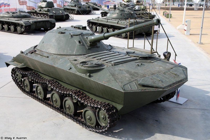
The K-90 tank was developed in early 1950 in Moscow by the Special Design Bureau of the Army Engineering Committee, under the leadership of A.F. Kravtsov. Components from the M-2 tracked artillery tractor and the YaAZ-200 truck were extensively used in the vehicle’s construction.
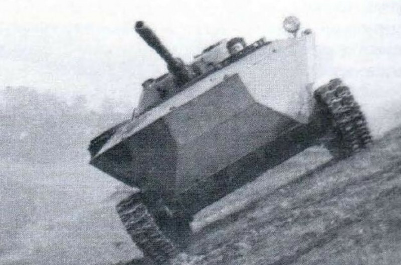
Two prototypes of the vehicle were manufactured by VRZ No. 2 of the GBTU, one of which underwent comparative range tests with the “Object 740” tank in July 1950. In terms of its amphibious capabilities, the reliability of its transmission components, and the protection of its amphibious propulsion system, the K-90 tank was inferior to the latter and was therefore not recommended for adoption into service.
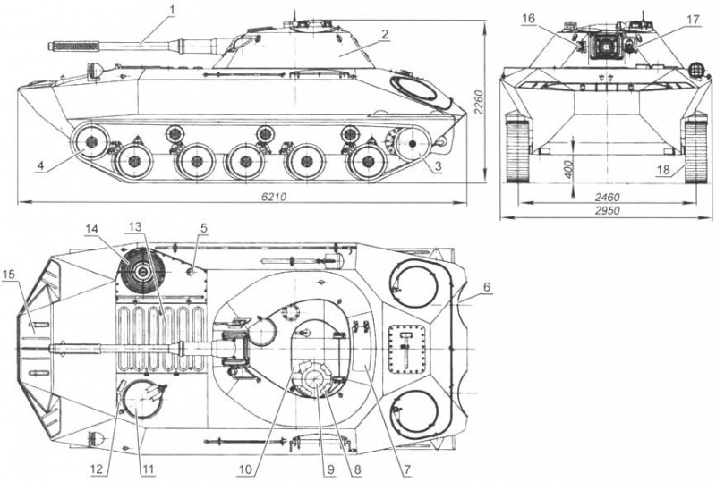
The K-90 experimental amphibious tank featured an original layout with the powerplant located at the front, the transmission components arranged in series along the hull’s longitudinal axis, and the fighting compartment offset toward the stern. As a result, when the gun was in the forward position, its barrel did not extend beyond the hull. The tank’s crew consisted of three men: the commander (who also served as gunner), the driver, and the loader. The control compartment was located on the left side of the front section of the hull, while the engine and its support systems were on the right. In the fighting compartment, the tank commander was positioned to the left of the gun, and the loader to the right.
To facilitate the work of the crew members stationed in the turret, the floor of the fighting compartment was attached to the turret ring via rods and rotated along with it. The commander’s and loader’s seats, mounted on special brackets, were installed on the rotating floor. The driver observed the battlefield through two prismatic sighting devices located at the front of the roof in front of his entry hatch, while the gunner observed through an MK-4 sighting device mounted in the turret roof, and the vehicle commander—through observation blocks located around the perimeter of the commander’s cupola.
The tank’s turret was equipped with a 76.2-mm LB-76T rifled gun and a coaxial 7.62-mm SG-43 machine gun (on the right, in a separate turret embrasure). When firing from the twin mount, a shortened TShK-9 telescopic articulated sight was used (on the left in a separate turret embrasure). The vertical elevation angles of the twin mount ranged from -4 to +25°. The gun was loaded manually, and its combat rate of fire reached 6–7 rounds per minute. The tank’s ammunition load consisted of 40 rounds for the gun and 1,000 rounds for the twin machine gun. Ammo racks with horizontally arranged artillery rounds were located near the loader’s workstation along the perimeter of the combat compartment’s rotating floor.
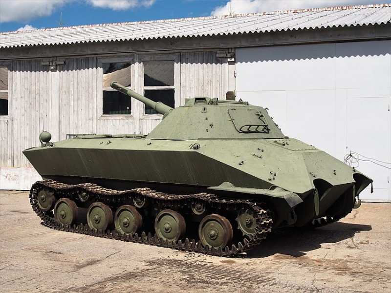
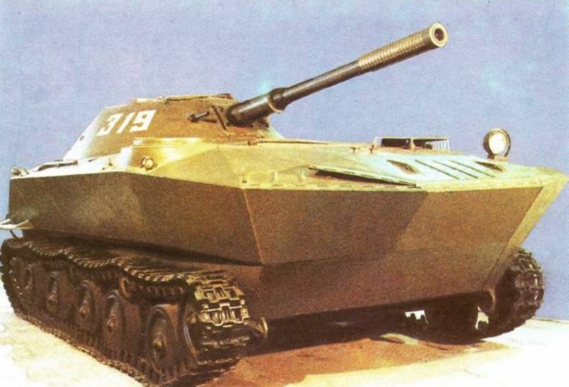
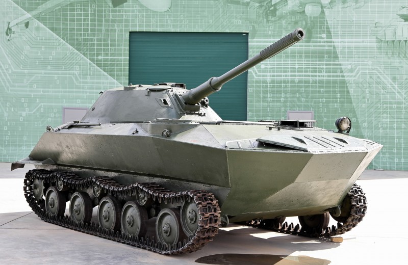
The tank’s armor provided protection against bullets and was made of rolled armor plates 4, 6, 8, 10, 12, and 15 mm thick. The maximum armor thickness on the front of the hull and turret was 15 mm. The hull had a streamlined shape that ensured minimal drag while afloat. On the front left side of the hull roof was the driver’s hatch, covered by a rotating armored flap; in the center—a hatch above the engine with armored covers over the cooling air intake openings, and on the right—a hatch with armored louvers for the cooling system fan to expel used cooling air.
In the upper part of the right side of the hull (in front of the turret) there was a hatch with a hinged cover for draining water that had entered the vehicle’s hull while crossing a water obstacle using the bilge pump. On the lower, sloped section of the starboard side was an opening for draining fuel. Eyelets were welded to the bow of the hull for attaching a removable, three-section wave-deflecting shield. The hull bottom featured cutouts for the propeller shafts and openings (on the starboard side) for the exhaust of engine gases.
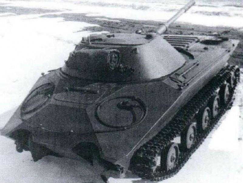
The conical turret was welded together from bent armor plates with varying angles of inclination relative to the vertical. The turret roof featured an entry hatch with an armored cover that opened forward; on the left side of the hatch was a fixed commander’s cupola equipped with observation devices. Behind the commander’s cupola, there was an opening in the turret roof for an antenna feed-through. In the front part of the roof, on the right, a turret fan was mounted, covered by armor protection; on its right side was an opening for firing personal weapons, which was closed by an armored plug. An emergency exit hatch was located in the rear wall of the turret.
The tank’s powerplant consisted of a liquid-cooled, two-stroke, four-cylinder YAZ-204 diesel engine with a power output of 103 kW (140 l.s.) at a crankshaft speed of 2,000 min, coupled with a manual transmission. The engine was started using a 5.5 kW (7.5 l.s.) ST-25 electric starter. In low ambient temperatures, a preheater—consisting of a boiler, a pump unit, a piping system, and electrical equipment—as well as an intake air preheater built into the engine’s supercharger receiver, facilitated engine starting. The engine’s lubrication system utilized a water-oil radiator, while the air filtration system featured a combined-type air cleaner consisting of a set of cyclones and two inertial oil traps. The fuel tanks had a capacity of 240 liters. The cruising range on the highway was 180–240 km, and on water, 90–100 km.
The transmission consisted of: a single-disc dry-friction main clutch (steel with Ferodo lining); a two-shaft automotive-type transmission providing five forward gears and one reverse gear; a transfer case, two propeller reverse gearboxes; a final drive (bevel reduction gear); two multi-disc dry-friction side clutches (steel-on-steel), used as a steering mechanism; two floating-type band brakes and two simple single-row side gearboxes. The transmission components were connected to one another by cardan shafts.
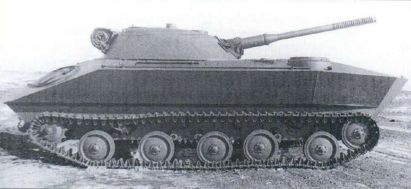
The suspension system utilized an independent torsion bar suspension with buffer travel limiters on the balance bars at their end nodes. Relative to the other suspension components, the balance bars of the third road wheels were arranged in an opposing configuration. The track drive assembly consisted (per side) of five single-groove stamped road wheels with external shock absorption (500 mm in diameter), a guide wheel (standardized with the road wheel) with a track tensioning mechanism, a guide skid mounted on four brackets and serving as support rollers, a rear-mounted drive sprocket with a non-removable ring gear, and a fine-link track with external shock absorption, 300 mm wide.
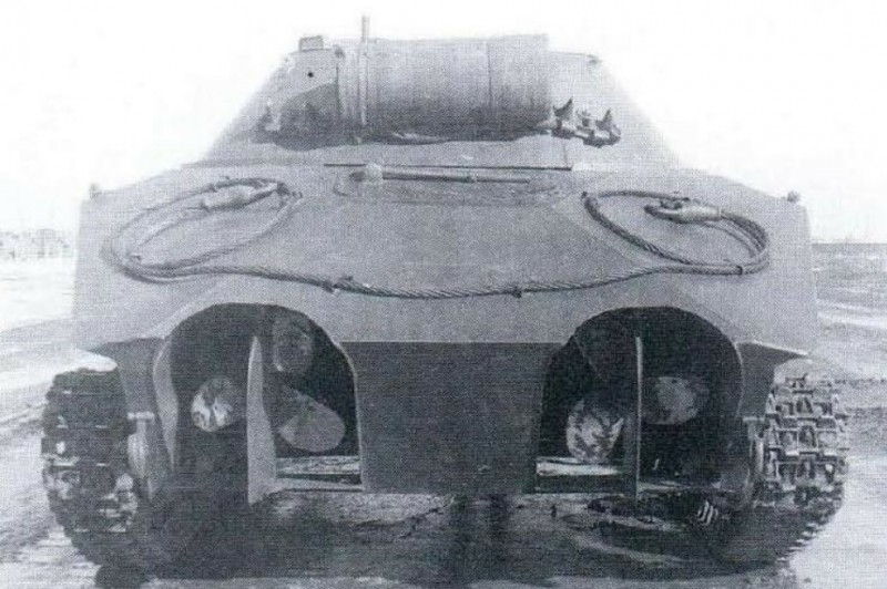
Propulsion at sea was provided by two 600-mm-diameter propellers, which were housed in recesses in the bottom of the hull at the stern. Power was transmitted to the propellers via reverse gearboxes. The reverse gear was conical, with a shift clutch that had no neutral position. The design of the transmission units allowed for the simultaneous operation of the tracked and water-jet propulsion systems. The tank’s turn while afloat was accomplished using two propeller rudders (mounted behind the propellers), which were controlled by a horizontally mounted steering wheel and a cable mechanism. The tank’s electrical system was designed using a single-wire configuration. The onboard electrical system operated at 24 V. The main sources of electrical power were two 6STE-140 batteries and a 1.5 kW GSK-1500 generator.
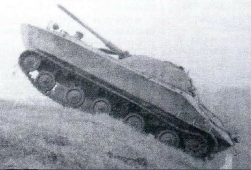
The tank was equipped with interior and exterior lighting systems, including road signaling lights. A 10RT-26 radio was installed for external communications, and a TPU-47 tank intercom system was installed for internal communications. The use of components from the M-2 series tractor and the YAZ-200 vehicle in the K-90 tank’s design made it simple and inexpensive to manufacture. However, the tank had a number of significant shortcomings, including poor amphibious capabilities, an unreliable transmission, unprotected propellers, and an unreliable mounting for the wave deflector.
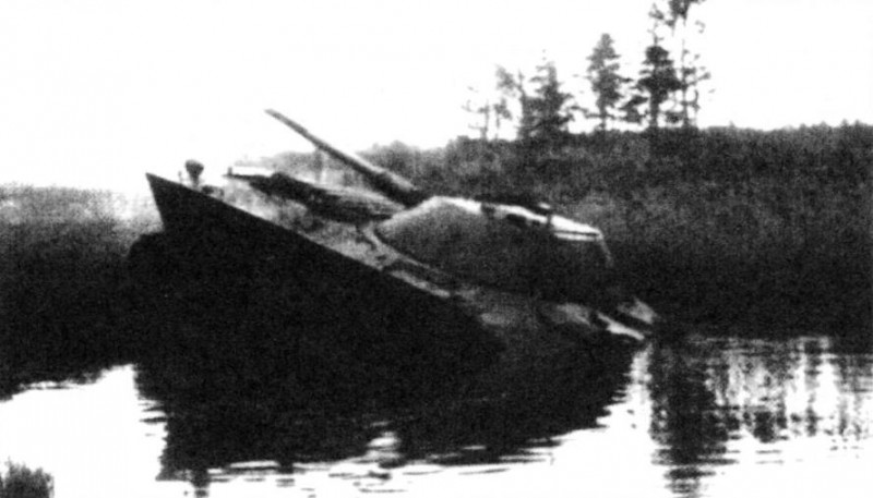
Following testing, the design of the turret and the vehicle’s running gear was improved. The shape of the turret entry hatch (which was made smaller) and the commander’s cupola were modified. The hatch cover now opens backward, so the antenna feed was moved forward (to the left of the commander’s cupola). Armor plating was installed over the sight aperture, along with a protective cover that opens from the inside. In the running gear, three (per side) all-metal, single-slope support rollers with a diameter of 250 mm were used in place of the guide skids. In addition, to protect the propellers, the steering rudders were designed as two hinged halves that covered the hull recesses when the vehicle was moving overland. The K-90 tank is currently on display in this configuration at the Museum of Tanks and Armored Vehicles in Kubinka.
Tactical and Technical Specifications of the K-90 Tank
- Combat weight — 10 metric tons;
- crew — 3 people;
- Weapons: 1 76.2-mm rifled cannon, 1 7.62-mm machine gun;
- armor protection — bulletproof;
- engine power — 103 kW (140 l.s.);
- maximum speed:
- on the highway – 34.3 km/h,
- on the water — 9.6 km/h.
Source — https://picturehistory.livejournal.com/4815141.html