Supermarine's Secret Projects: Flying Boats. Part 11: Four-Engine Military Flying Boats

This is the next installment in a series of articles that are translations of chapters from a book by British aviation historian Ralph Pegram.
In 1932 and during the following two years, the planning bodies of the Ministry of Aviation found themselves in a difficult position. On February 2, 1932, a conference on arms reduction and limitation was convened in Geneva after more than a decade of little progress by the League of Nations on this issue. The conference was chaired by Arthur Henderson, a Labour Party member of Parliament and former foreign secretary. The British Government of National Unity—an alliance of parties led by Prime Minister Ramsay MacDonald, a former Labour prime minister who had been expelled from the party following the formation of the Government of National Unity— — supported the conference’s objectives and also sought to preserve Great Britain’s status on the world stage.
Naturally, there was a great deal of skepticism and no small amount of opposition, but the government’s policy was to refrain from any noticeable major rearmament efforts while the conference was in session. In fact, it was the British delegation that proposed limiting the empty weight of military aircraft to three metric tons (6,720 pounds), and the Ministry of Aviation was forced to adjust its requirements in line with this initiative, no matter how strongly the Ministry itself and the aircraft manufacturers objected.
Strange as it may seem, fortunately, flying reconnaissance boats were not included in the scope of this proposal, and therefore their development could continue without any particular concerns about possible restrictions. Thus, when considering what type of aircraft should be assigned to long-range coastal defense units, the requirements for these aircraft went far beyond the limitations of the British government’s proposal at the peace conference, even if this aircraft was also intended to perform purely bombing missions. The fact that the reconnaissance aircraft under development could easily be converted into a dedicated bomber was deliberately ignored. Such is the Machiavellian nature of politics.
In November 1933, as part of a competition organized by the Ministry of Aviation, Specification R.2/33 was issued. The technical requirements of OR.8 concerned
“long-range, four-engine, general-purpose boat-type seaplane,”
capable of carrying a combat load consisting of four 500-pound (227 kg) bombs or eight 250-pound (113 kg) depth charges. As a temporary measure, the Ministry of Aviation issued specification R.3/33 for the Short Singapore II flying boat; four prototypes were ordered in 1933, followed by 33 production aircraft in 1934. The Singapore III flying boat, equipped with four Rolls-Royce Kestrel engines in two tandem pairs, was generally larger than the Supermarine Stranraer, but carried the same bomb load and had poorer flight performance. In essence, the Singapore III flying boat—which became obsolete immediately after entering service in January 1935—was a stopgap measure pending the arrival of new, modern flying boats.
Before beginning serious work on a project that met the requirements of Specification R.2/33, Reginald Mitchell consulted his doctor in August for advice, as he had been experiencing bouts of abdominal pain. After Mitchell was referred to a specialist, the aircraft designer was diagnosed with colon cancer and told that immediate surgery was required. For more than half a year after the surgery, Reginald Mitchell was unable to work in the office, but during his recovery he remained involved in all of the company’s key decisions, holding daily meetings with his deputies from his home.
Specification R.2/33 did not specify whether the aircraft should be a biplane or a monoplane, but the required performance characteristics and the general design trend in the industry strongly suggested that a monoplane was the appropriate choice. The specification also did not prescribe a specific engine type; the only stipulation being that any British engine could be selected provided it had undergone 100 hours of continuous operation testing or, more likely, would have passed such testing by the time the aircraft was already in service.
Even before the specifications were released, Supermarine’s main competitors had already begun developing design solutions that could be revised to meet the requirements. Saunders-Roe, in collaboration with General Aircraft Limited, was working on equipping the A.29 Cloud flying boat with a single-spar wing and stabilizing sponsons—an experimental project called for in the Ministry of Aviation’s Specification 18/32. Blackburn was developing several variants of civilian and military one-and-a-half-wing aircraft powered by Junkers Jumo diesel engines and submitted models for testing in the RAE wind tunnel. Short Brothers may have been less prepared, but on November 30, 1933, the experimental S.18 Knuckleduster monoplane flying boat, developed in response to the requirements of Specification R.24/31, made its first flight. In addition, a design for a twin-engine monoplane flying boat was taking shape on the drawing boards of Short Brothers’ designers; this design would later become the lower section of the Mayo Composite combined aircraft, developed under specification 13/33, and within the company itself, serious changes in the direction of flying boat design were also being actively considered.
Supermarine was in a very strong position to design a wing for a large flying boat monoplane. The company had already manufactured and tested a single-spar wing for the Air Yacht flying boat in 1930, and the RAE conducted strength tests on a scaled-down model to evaluate the torsional strength of the cantilever single-spar wing for the giant Type 179 Giant flying boat. A smaller cantilever wing was built for the Type 224 fighter when its construction was nearing completion.
It was almost a given that a single-spar wing design would be incorporated into the flying boat under development, as this would allow Reginald Mitchell to choose the Rolls-Royce Goshawk as his preferred engine and to once again use a D-shaped caisson as a steam condenser. Although Mitchell’s experience with stabilizing sponsons installed on the Air Yacht flying boat had not been entirely positive, he must have still believed that this concept offered advantages that made sponsons preferable to underwing floats, and that the numerous problems encountered with the Air Yacht had been resolved to such an extent that he was prepared to incorporate sponsons into the design of a new seaplane, which received the internal designation Type 232.
In the initial layout drawings, which were prepared in April 1934, the shape of the lower hull was identical to that of an enlarged Stranraer boat hull, but with the addition of an upper deck on which the pilot’s cockpit was located directly in front of the wing console roots. The enclosed cockpit, set slightly back from the nose, placed the pilot a few feet behind the plane of the propeller blades and close to the inner engine discs. At first glance, this was far from ideal and could potentially be distracting due to the stroboscopic effect during long flights.
The navigator’s observation post was located in the lower part of the main fuselage, directly beneath the discs swept by the propellers—a spot exposed to the highest noise levels— however, his compartment, complete with a table holding aeronautical charts, was located under the wing next to the flight engineer’s workstation. A staircase led from this control compartment to the pilot’s cockpit, but the navigator sat outside the pilot’s field of view and, consequently, had no direct visual contact with him. Four berths with storage lockers underneath were provided for the crew.
The defensive armament consisted of a machine gun mounted in a defensive position on the upper surface of the hull and two side defensive positions near the hinged observation ports at the rear of the hull. The machine gun mounted in the defensive position at the rear of the hull could be protected by a helmet-shaped cover that could be closed when the weapon was not in use. The rotating turret mounted at the forward end of the fuselage could accommodate either a Lewis machine gun or a 37-mm COW automatic cannon. At the time, the latter were popular with the Royal Air Force command and were considered by them as standard armament for patrol flying boats, since these automatic cannons allowed aircraft to engage small vessels and submarines operating on the surface. Before this concept was rejected, a COW cannon was installed in the nose of the Blackburn Iris III flying boat. Beneath the nose turret was a top-mounted bomb-aimer hatch, typical of Supermarine—a simple system used on the Scapa and Stranraer flying boats.
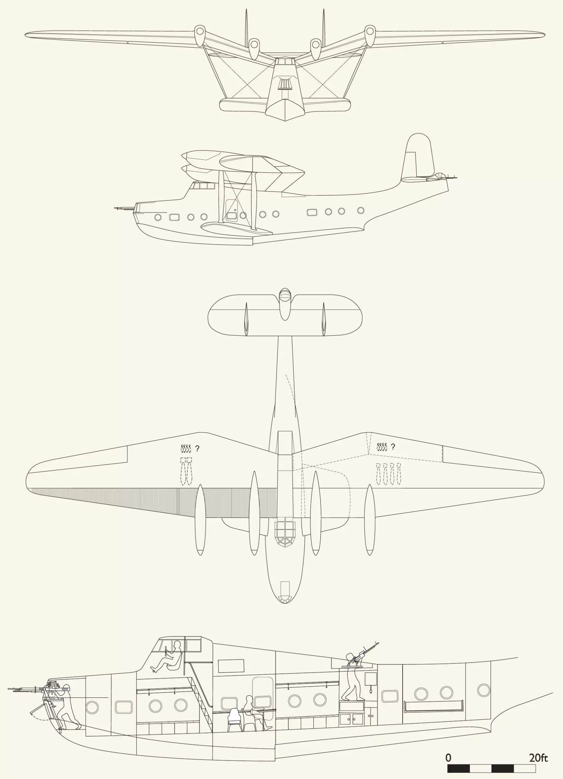
the Type 232 four-engine reconnaissance flying boat, developed in response to the requirements of Specification R.2/33
The sponsons had a slight trapezoidal shape. From the root sections to the tips, there was a decrease in relative thickness and an increase in the angle of installation; the latter feature was observed on the Air Yacht flying boat after it was modified. Unlike the rectangular sponson tips on the Air Yacht, the sponson tips on the proposed hydrofoil design were rounded. As on the Air Yacht, the main fuel tanks of the proposed hydrofoil were located inside the sponsons.
To protect the propellers from splashes, the inner sections of the wing cantilevers—to which the engines were attached—were given a significant transverse V-angle. This design feature also facilitated the drainage and accumulation of condensate from the cooling system. The inner sections of the wing cantilevers were trapezoidal in shape and had the following relative thicknesses: 10% at the root sections and 18% at the outer engine nacelles. The outer sections of the wing cantilevers tapered toward the wingtips. The Goshawk engines were located on the inner sections of the wing consoles, forward of the leading edge and slightly above the chord centerline; the engines were mounted in pylon-mounted nacelles, which also housed the fuel, water, and oil tanks.
It is interesting to note that the wing consoles were not designed to be fully cantilevered—which, as is generally acknowledged, would have been difficult due to the thin cross-section and reduced chord length at the wing roots—and were reinforced with struts. A pair of struts extended from the sponson tips to each wing cantilever, with the rear strut attached to the wing spar and the front strut to the engine nacelle of the outboard engine. For additional strength, the pairs of struts were connected by conventional diagonal wire braces, and the front struts were similarly attached to the fuselage by load-bearing and reverse struts.
As with the Type 179 Giant flying boat, the wing of the proposed craft—from the leading edge to the spar, located approximately 30% of the chord length—formed a steam condenser for the cooling system and featured a corrugated skin. Steam from the engines flowed into the condenser immediately behind each engine and, as expected, then completely filled the interior space across the entire wingspan due to natural expansion and turbulence; it seems doubtful that the outer sections of the condenser could have contributed significantly to the cooling.
The condensed water then flowed downward by gravity and collected in a hot-water tank at the root of the wing, from where it could be returned to the engines. In principle, this seemed effective, and small-scale tests revealed no problems, but operational experience with the Type 224 fighter, which began test flights in February 1934, soon showed that locating the hot-water tank below the engine’s water intake level could all too easily lead to problems, since the pressure differential at the inlet of the water pumps could cause the hot water to spontaneously re-boil if it had not yet cooled sufficiently. In this case, steam entering the pumps would disrupt the water supply and possibly cause air locks if air were drawn in along with the steam.
The bomb bays were internal and located at the roots of the outer sections of the wing cantilevers, behind the spar. Each wing pylon could carry two 450- to 550-pound (204- to 250-kg) bombs or depth charges, or four 100- to 250-pound (45- to 113-kg) bombs. Behind the main bomb bays were smaller compartments designed to hold four 20-pound (9 kg) bombs.
Most likely, the flight performance calculations for this initial design variant proved disappointing, as it underwent a thorough redesign and was scaled down in July. Although the fuselage largely retained its original shape, its length was reduced, and the gliding underside became narrower. Similarly, the wing was reduced in both wingspan and chord length, although the wingspan of the inner sections of the wing had to remain the same to maintain the appropriate distance between the engines. Split flaps were installed between the ailerons and the fuselage on both the inner and outer sections.
The design documentation included numerous drawings showing the firing sectors, internal layout, engine mounting details, mooring equipment, etc. It was understood that an official brochure would be prepared for the competition, but no records were found confirming that the Ministry of Aviation had received such a brochure.
While the initial set of layout drawings was being prepared, a second set of documentation, designated Type 239, showed a similar flying boat but of larger dimensions to accommodate Rolls-Royce Merlin engines with an evaporative cooling system.
Finally, Supermarine played it safe and developed a design for a biplane flying boat, designated Type 238, that met the requirements of specification R.2/33. Essentially, the Type 238 flying boat was a scaled-up version of the Stranraer boat, equipped with four Bristol Perseus radial engines.
In 1934, the Ministry of Aviation awarded contracts for the development of prototypes to Saunders-Roe (for the A.33) and Short Brothers (for the S.25, which would later be designated the Sunderland). Both flying boats were equipped with four Bristol Pegasus radial engines. At that time, Short Brothers was clearly on the rise in the field of large four-engine flying boats; the company had secured contracts for the S.20, the lower section of the Mayo Composite aircraft, the S.23—which Imperial Airways put into service as the Empire Class “C” flying boat—and, finally, the S.25 Sunderland. All three types were based on the same fundamental design—a set of innovative ideas developed by a team led by Arthur Gooz. Each of these three flying boats featured a tall, narrow hull, a cantilever wing with box-shaped spars, large flaps that increased the wing area, and shock-absorbing underwing floats. Over the next ten years, this set of ideas became a winning formula and led to numerous orders.
Saunders-Roe continued to develop its concept of a flying boat with a single-spar wing and stabilizing sponsons, resulting in the A.33. The high-mounted parasol wing was additionally secured by a system of struts extending from the upper surfaces of the sponsons, forming a parallelogram-shaped mounting without any connection to the upper part of the hull. This allowed for a low-profile hull and, consequently, reduced drag. However, the seaplane suffered from stability issues and, during its fifth test flight, was thrown into the air after striking the boat’s wake. The flying boat entered a stall and made a hard landing, during which the wing was seriously damaged; the A.33 flying boat met the same fate as the Supermarine Air Yacht. Since, at the time of the accident, the A.33 flying boat was already a year behind its competitor, the S.25 Sunderland, the management of Saunders-Roe decided to halt repairs and cancel the program.
If Supermarine had built and test-flown the Type 232 flying boat, it would inevitably have had to be fitted with new engines even before construction was completed. The Goshawk aircraft engine failed to live up to expectations in its intended role as a fighter engine, and Rolls-Royce discontinued its development in early 1935, several years before Supermarine could have completed the aircraft. At the same time, Rolls-Royce abandoned the evaporative cooling system for the engines under development in favor of cooling with glycol or a water-glycol mixture.
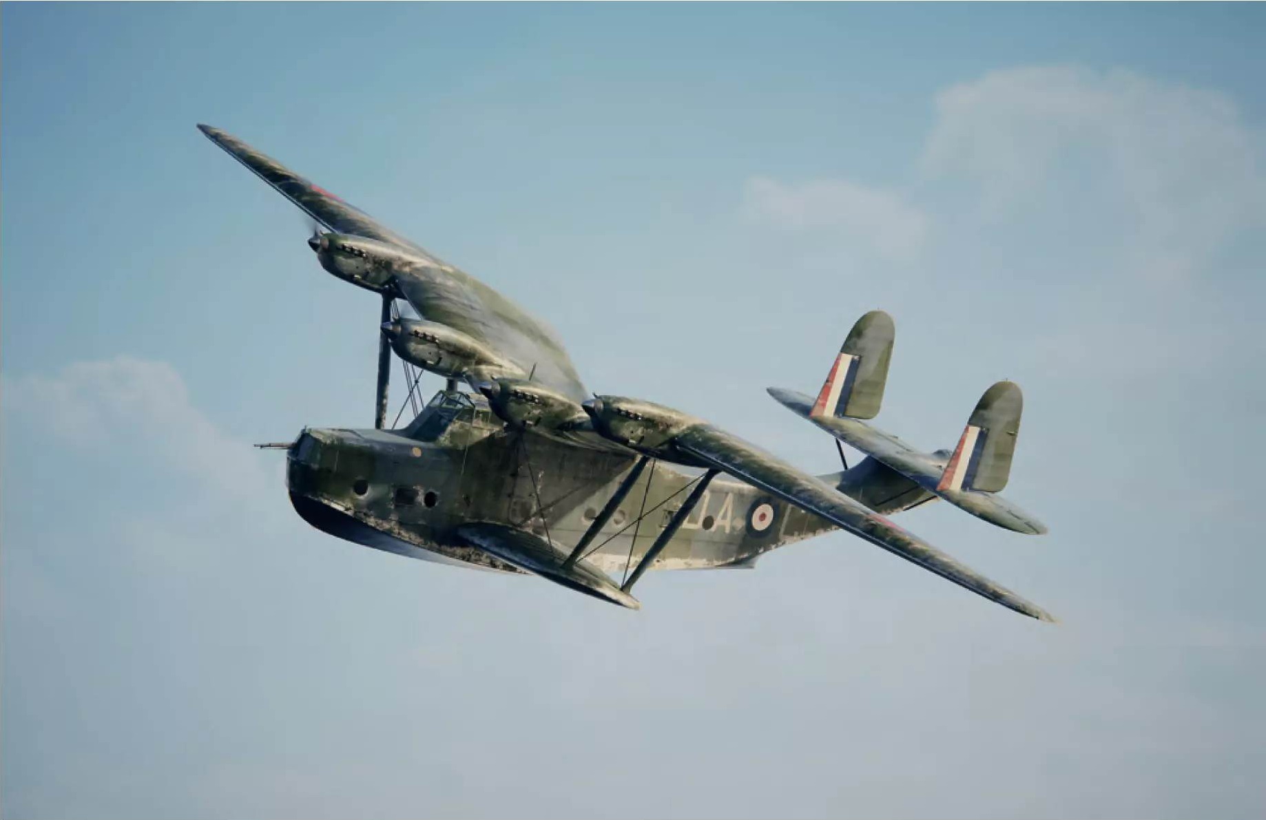
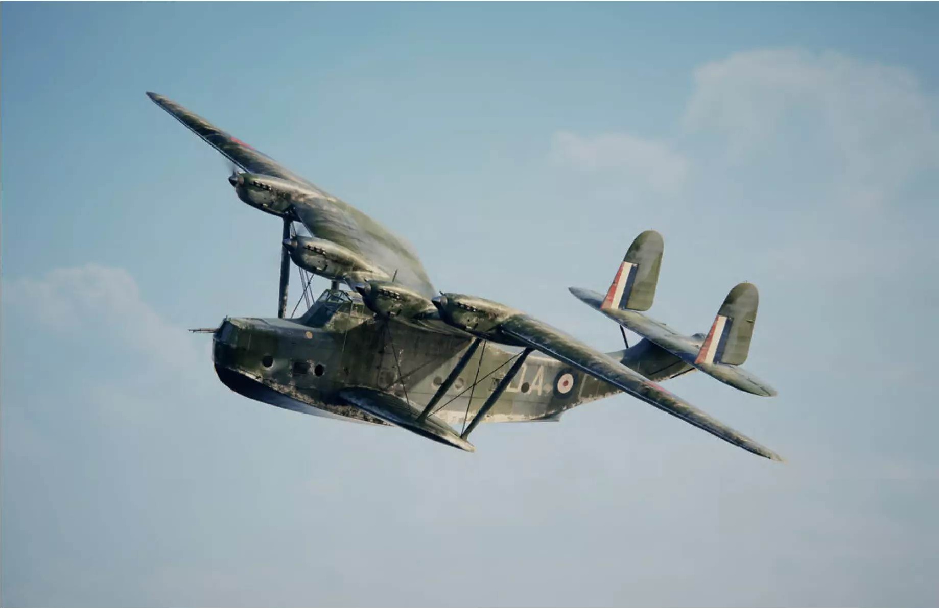
The Type 232 reconnaissance seaplane was intended to conduct long-range patrol flights over the North Atlantic to protect merchant ship convoys. Illustration by Matt Painter
In the article “What’s Happening in Air Transport Today?”, published in October 1934 in the *Daily Mirror*, Reginald Mitchell wrote:
“Evaporative engine cooling is yet another innovation with great potential… Its advantages are so obvious that this [cooling] system is sure to be widely used in the future, but its practical application has long been delayed.”
A few months later, Reginald Mitchell would come to realize he was wrong.
In any head-to-head competition, the Type 232 flying boat’s swept-back wing would have had worse aerodynamics than that of the Sunderland, and there were no other design features in Supermarine’s flying boat that could have been more advanced. Following the cancellation of the ill-fated Type 179 Giant project, this was Supermarine’s second unsuccessful attempt to enter the field of large flying boats, and Reginald Mitchell and his team would have to significantly improve their professional skills to restore the company’s position as a leading seaplane manufacturer.
Before we examine Supermarine’s subsequent attempts to win another competition to design a flying boat, we should pause to consider the commercial success that was achieved alongside these major projects.
Replacing the Seagull Flying Boat. Part 2
After efforts to generate interest in the Type 181 flying boat on the civilian market failed, and the Royal Australian Air Force (RAAF) declined to place an order for its military version, it seems entirely logical that Supermarine abandoned this line of development. However, Reginald Mitchell did not want to abandon the flying boat class, which he believed to be useful, and, moreover, the RAAF’s stated requirements for a new seaplane remained unmet. While Supermarine’s design team focused primarily on developing an attractive replacement for the Southampton flying boat, Mitchell continued to work actively on a design intended to replace the RAAF’s Seagull III.
Following the acquisition of Supermarine by the Vickers Group and the layoffs caused by the onset of the Depression, Robert McLain began downsizing Supermarine’s workforce to bring it more in line with Vickers Group practices. Even some of those who worked at the company during that period acknowledged that after World War I, the company’s development had been rather chaotic. The design bureau did not have a systematic catalog; and drawings were simply numbered sequentially in the order in which they were created, so that finding all the drawings related to a specific project was a tedious task, as they were stored interspersed with drawings pertaining to other projects.
The handling of containers holding components for aircraft under construction was organized just as illogically, since their placement and stocking relied to a certain extent on the warehouse manager’s memory. Many Supermarine employees were upset by the arrival of the Vickers Group and were not fully prepared to cooperate with the new management, which led to several rounds of layoffs, including in departments headed by Reginald Mitchell. As the company’s fortunes improved, it began recruiting designers and draftsmen with experience at other companies. Among those who joined the design team at that time was shipbuilder William Munro (William Munro), who had trained at the Vickers shipyard in Barrow and who later worked on float designs for Gloster’s racing seaplanes. William Munro then moved to Canada to work at a local division of the Vickers Group, and then to the United States, where he served as chief engineer at the American company Towle, working on the development of flying monoplane boats—seaplanes similar in style to the Saunders-Roe Cloud.
When William Munro began working at Supermarine in 1931, he prepared several layout drawings of civilian and military flying boat monoplans—likely on a theoretical basis and to demonstrate his capabilities. William Munro was then assigned to the design team tasked with developing a replacement for the Seagull III flying boat, where his knowledge and experience were to have a significant influence on the direction of further design work. Instead of resorting to a simple modification of the Type 181, the team decided to start from scratch and, adhering to the basic formula of a single-engine biplane with a pusher propeller, developed an extremely simple metal fuselage containing nothing but the necessary curved panels.
The gliding hull consisted of flat panels based on patents held by Saunders-Roe. The hull was reinforced so that the flying boat could be launched from a catapult. The rearward-folding wing consoles of the single-strut biplane featured a mixed wood-and-metal construction. The tail unit consisted of a single keel with a stabilizer attached to the upper part of the keel. The engine—originally a Rolls-Royce Kestrel—and its pusher propeller were mounted in the center of the wingspan, and the struts supporting the engine nacelle also served as a support for the central section of the wing. The engine nacelle was slightly offset to the left to compensate for the torque exerted by the propeller on the tail unit. A completely new and simple design of a single-point retractable landing gear, equipped with an oil shock absorber and mounted on a hinge at the top, was developed for this project. When retracted, the struts rotate 90 degrees away from the fuselage and are fully stowed in recesses in the lower wing. Before the aircraft was built, the engine was replaced with an air-cooled Bristol Pegasus radial engine. Thus, the Type 223, the Seagull V, was born.
In light of this, the question of the company’s internal designation system arises once again: what exactly is the Seagull IV? Most likely, this was an unofficial designation given to the Type 181 flying boat, although there do not appear to be any records that could confirm this.
The Seagull V was yet another project that received personal support from Sir Robert McLean, who approved funding for the prototype’s construction even before an order was received from the RAAF, whose leadership was not yet convinced of the design’s merits. This proved to be yet another wise move, since as soon as the prototype performed well in tests—including launches from the RAE catapult—Supermarine received an order for 24 flying boats, the first of which entered service in June 1935.
Although the Royal Air Force was initially skeptical of the Seagull V, it was impressed by the flying boat’s performance. In May 1935, an order was placed for an initial batch of five aircraft, which were given a new designation and for which Specification 2/35 Walrus was issued. Later that same year, another 36 flying boats were ordered.
It was inevitable that civilian versions of the Seagull V flying boat would be developed, although the spartan interior of a simple metal box was not particularly well-suited for civilian use. The first proposal was the Type 225, developed in 1932 and equipped with a Kestrel engine; later, in 1934, a variant with a Pegasus radial engine was introduced, adapted to meet the needs of Jersey Airways. None of them were ever built.
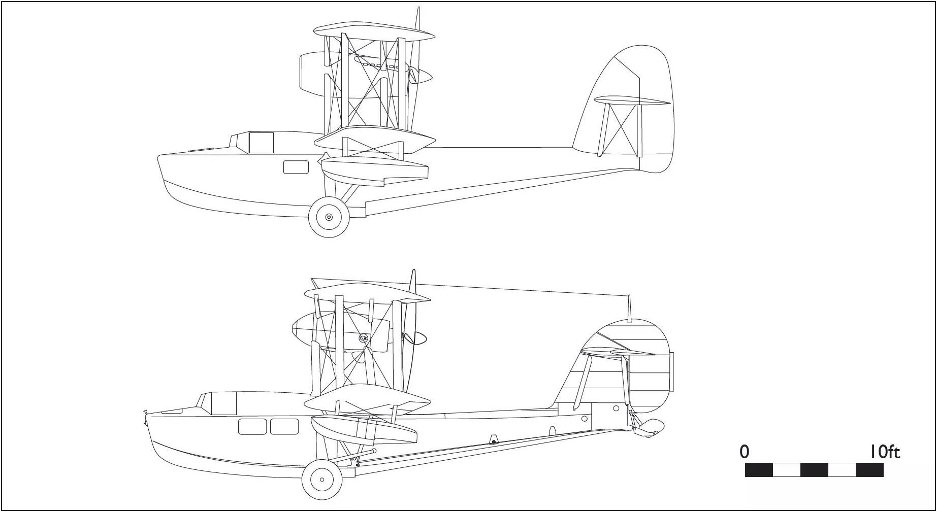
The Seagull V was a simple military amphibious flying boat and was not particularly well-suited for use by passenger airlines. Nevertheless, two options were proposed: the first was the Seagull V with a Kestrel engine in 1932, and the second was a modified version of the Walrus, which was offered to Jersey Airways in 1934.
источник: Ralph Pegram «Supermarine Secret Projects Volume 1 – Flying Boats», pages 84-89
This translation was first published at – https://vk.com/@710541705-supermarine-secret-projects-flying-boats-11