The History of External Tail Structures: From World War II Research to SpaceShip III. Part 3

Across the Atlantic
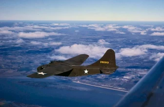
It is claimed that, in parallel with the early work conducted in Europe described in the previous sections of this article, research into external tail surfaces was being carried out at Wright Field Air Force Base in the United States. The first results of this research emerged in a somewhat different context. Aviation engineer Charles H. Zimmerman worked on a flying wing with a disc-shaped wing featuring propellers mounted at the wingtips. These propellers rotated in such a way as to counteract the powerful vortex created by the air flowing around the wing tip. Charles Zimmerman managed to pique the company’s management’s interest, and the U.S. Navy funded the development of the Vought V-173 Flying Flapjack experimental aircraft. The V-173’s design featured external horizontal stabilizers attached to the rear of the elliptical wing. The “Flying Flapjack” flew successfully in 1942, predating the Škoda-Kauba SL6 by a year or two. Thus, this is the earliest example known to the author of flight with an external tail unit. Subsequently, Zimmerman and Vought developed the XF5U fighter prototype. Although this aircraft was built, the war had ended, and as a result of postwar cutbacks in military programs, the XF5U program was canceled before the prototype could even take flight.
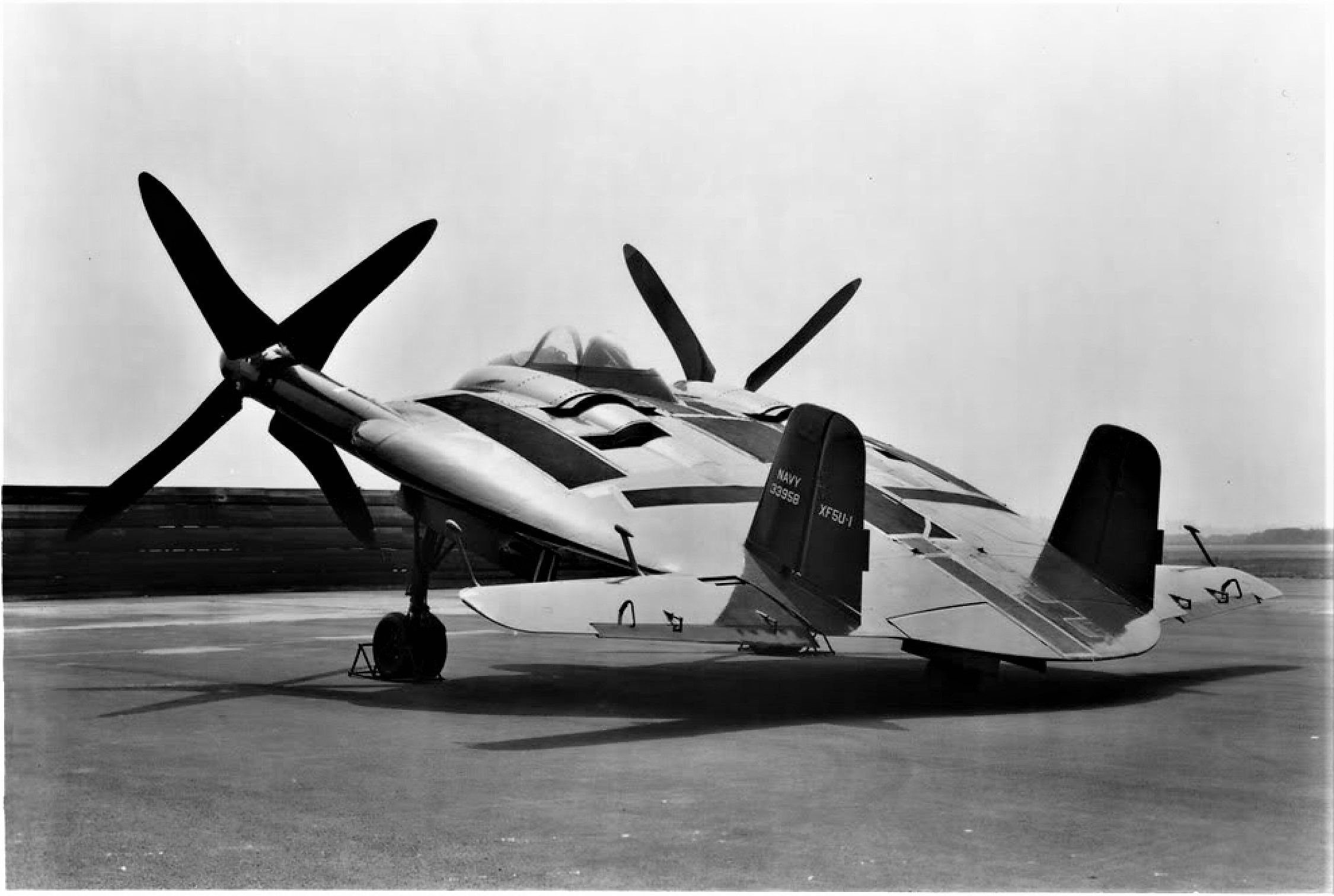
The Vought XF5U experimental fighter, designed by Charles Zimmerman, was a further development of his experimental V-173 Flying Flapjack aircraft and featured a wing with a very low aspect ratio. Both aircraft featured an external tail unit, as shown in the photograph of a completed XF5U. The aircraft was powered by two air-cooled Pratt & Whitney R-2000 Twin Wasp radial engines, which drove massive propellers mounted on extended shafts. Photo from the archives of *The Aviation Historian* magazine, hdpic.club
Richard Vogt and Hans Amtmann, the head of the preliminary design department who reported to him, were among the scientists, designers, and engineers detained during Operation Paperclip and given the opportunity to continue their professional careers in the United States. Although none of them appears to have been directly involved in work on external tail surfaces thereafter, the community of aircraft designers—and especially many German expatriates—remained close-knit. In the late 1950s and early 1960s, engineers at the National Advisory Committee for Aeronautics (NACA [NACA]), as part of a research program to develop configurations for supersonic flight, investigated the principles of external tail surfaces, combining them with the results of German wartime aerodynamic research. The need for low drag and clean, streamlined shapes was even more pressing beyond the “sound barrier.”
Groups of NACA specialists conducted a series of analyses and wind tunnel tests on models at both subsonic and supersonic speeds. In one line of research, a comparison was made between external tail surfaces and the “duck” aerodynamic configuration, which was distinguished by its forward-mounted horizontal stabilizer, while another line of research focused on studying external tail surfaces for use in the design of a supersonic airliner. The term “external tail” was apparently coined by NACA staff for this study, recognizing it as a distinct tail configuration rather than a variant of a tailless aircraft. However, this is all a matter of semantics; from the very beginning, the stabilizer was recognized as functioning as part of the tail assembly.
In 1958, NACA became part of a new agency—the National Aeronautics and Space Administration (NASA [NASA]), which began developing the concept of a “carrier body” as a reusable spacecraft. The agency’s first full-scale experimental glider, the M2-F1, featured an external horizontal stabilizer with cantilevers mounted midway up the height of its keels. The keels were located at the rearmost ends of the conical fuselage; their outer surfaces were flush with the fuselage sides, while the struts of the outer horizontal stabilizers extended directly from the keels. The M2-F1 took to the air for the first time on August 16, 1963. As the design evolved, the outer horizontal stabilizer proved unnecessary, and it was removed on later aircraft.
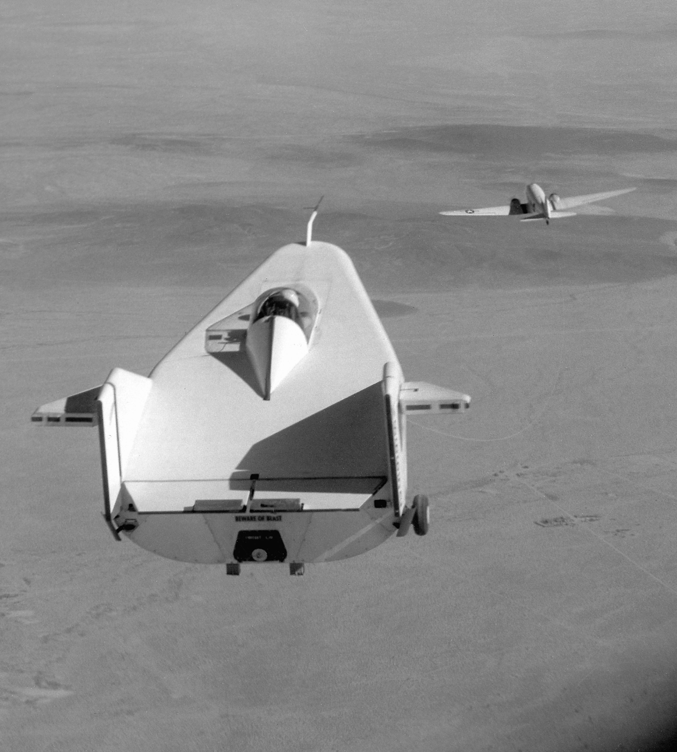
NASA’s M2-F1 “flying bath” was a “wing-in-body” aircraft designed to investigate the possibility of a spacecraft making a horizontal landing after re-entry into the atmosphere. External horizontal stabilizer struts were mounted on its keels. Between 1963 and 1966, the NASA M2-F1—carried to high altitudes by a C-47 transport aircraft—completed approximately 77 flights, gliding and landing on the runway at Rogers Dry Lake (Rogers Dry Lake), California. NASA photo, upload.wikimedia.org
Vought also did not overlook the external tail surfaces. By 1959, the company had become a division of Ling-Temco-Vought (LTV), and a group led by Byron R. Winborn (Byron R. Winborn), whose goal was to explore the possibility of developing a propulsive-wing aircraft (PWA) powered by a turbojet dual-circuit engine. The concept for the aircraft under development was named the Propulsive Wing Airplane; the plan was to use a rotating rotor to generate thrust and lift. The project itself was named ADAM (Air Deflection And Modulation). ADAM was distinguished by several small-diameter engines mounted on the inner part of the wing or inside it, behind which was a large and powerful flap. Soon, the development team discovered that the airflow conditions would render conventional tail surfaces ineffective; therefore, in 1960—largely for the same reason as the SNCASE consortium— the aircraft was equipped with an external tail unit. Numerous wind tunnel studies conducted in subsequent years led to a continuously evolving design, which was broadly grouped into the ADAM I, II, and III generations.
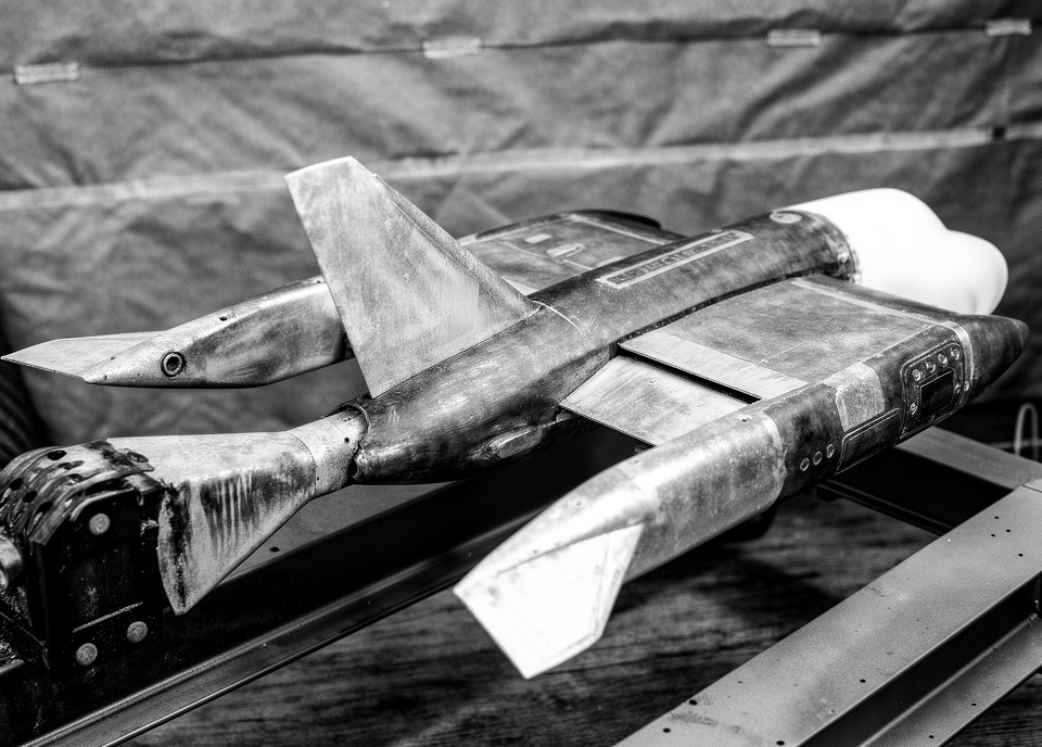
A wind tunnel test model of the Vought ADAM II project, which was equipped with external horizontal stabilizers mounted on short struts extending rearward from the trailing edge of the wing. Vought proposed using the ADAM system for all types of aircraft, from single-seat fighters and attack aircraft to large military and civilian transport aircraft. Photo courtesy of NASA. Image processed by lmarena.ai
Among other things, the LTV development team explored a V-shaped external tail configuration but later reverted to a slightly more traditional split stabilizer with two keels. In 1964, LTV patented the use of an external tail unit in combination with flaps on the trailing edge to vary the effective wingspan. The idea represented a step forward from Roger Robert’s original concept: the center of gravity was shifted even further aft; during normal flight, the tail would generate lift, and as a result, the effective wingspan would equal the aircraft’s full width. When a sharp maneuver was required, the flaps would partially deploy, increasing the wing’s lift in such a way as to relieve the tail from its load-bearing role—so that it would no longer assist the wing—thereby reducing the effective wingspan to the width of the spars. By 1965, LTV was ready to patent the Propulsive Wing Airplane concept.
During the course of the program, LTV conducted numerous design studies for both the U.S. Army and the U.S. Air Force, including the ASR 3-60 requirements for the Army and the SR-175 requirements for the Air Force, as well as its own V-460 design proposal. LTV then submitted a design proposal for the LTV-468 reconnaissance and strike aircraft and conducted a design study for a short- to medium-range passenger aircraft, after which the company returned to projects involving close air support and strike aircraft. Wind tunnel testing continued until 1970.
British Aeroelasticity
Ever since the Hawker Siddeley Harrier vertical/short-takeoff-and-landing (V/STOL) fighter made its debut in the late 1960s, British designers have been working on its supersonic successor. After the P.1154 program was canceled, the developers of this project at the British Aerospace design bureau in Kingston (BAe, nationalized in 1977) developed a long series of advanced short-takeoff and vertical-landing (STOVL) fighters throughout the 1980s, culminating in the P.1216 series. This series of designs was based on the concept of wing-tip booms to which the external tail unit was attached. It was one of the first projects in the United Kingdom to use computer-aided design (CAD) technology in combination with more traditional methods of creating engineering drawings.
For the most part, the P.1216 family of designs did not have full-fledged external horizontal stabilizers, since the beams were positioned only partially along the wing; therefore, the external tailplane was located within the wingspan of the wingtips. The development team in Kingston was aware of earlier work on external tail surfaces—although this was likely a case of convergent evolution, as the wingspan of the P.1216 was nearly identical to that of later variants of the ADAM III strike aircraft project—and was able to capitalize on what might be described as a “semi-external tail.” For example, the specially selected aeroelasticity of the inner carbon-fiber wing made it possible to create a tail unit that amplified the effect of the outer wing’s ailerons. The outer tail unit was designed to respond to the vortex trail from the aileron by altering its own lift, thereby rotating the spar and the inner wing to advantageously change the angle of attack of the outer wing. Thus, by moving the wing tips, the ailerons, and the tail assembly outward, the wing’s flexibility was transformed from a disadvantage into an advantage.
One variant, briefly studied in 1982—the P.1219—had a full external tail assembly. This design was essentially a P.1216 with the outer wing section removed to save weight. In the P.1219 design, the spars were moved further aft, and the total wingspan, including the external tail, only slightly exceeded that of the P.1216 design. However, the main wing area was still reduced. This was considered unacceptable, as it negatively affected takeoff and landing performance and reduced the steady-state turn rate. As a result, the project was not pursued further and was rejected because it did not meet the primary design objective—the creation of a full-fledged fighter. Even though it was rejected, this study is of particular interest because, on the one hand, it represents a repeat (following Blohm und Voss) use of an external tail unit to ensure high maneuverability and, on the other hand, represents the antithesis of Vought/LTV’s ideas regarding a variable-span wing. Given the design specifications of wartime projects, it is a great pity that a more advanced version of the P.1219—with a larger wing area and a more optimally configured external tail unit—was never realized. Its weight and aerodynamic efficiency would have provided a clear comparison with the main development line, which continued for another six years before being canceled.
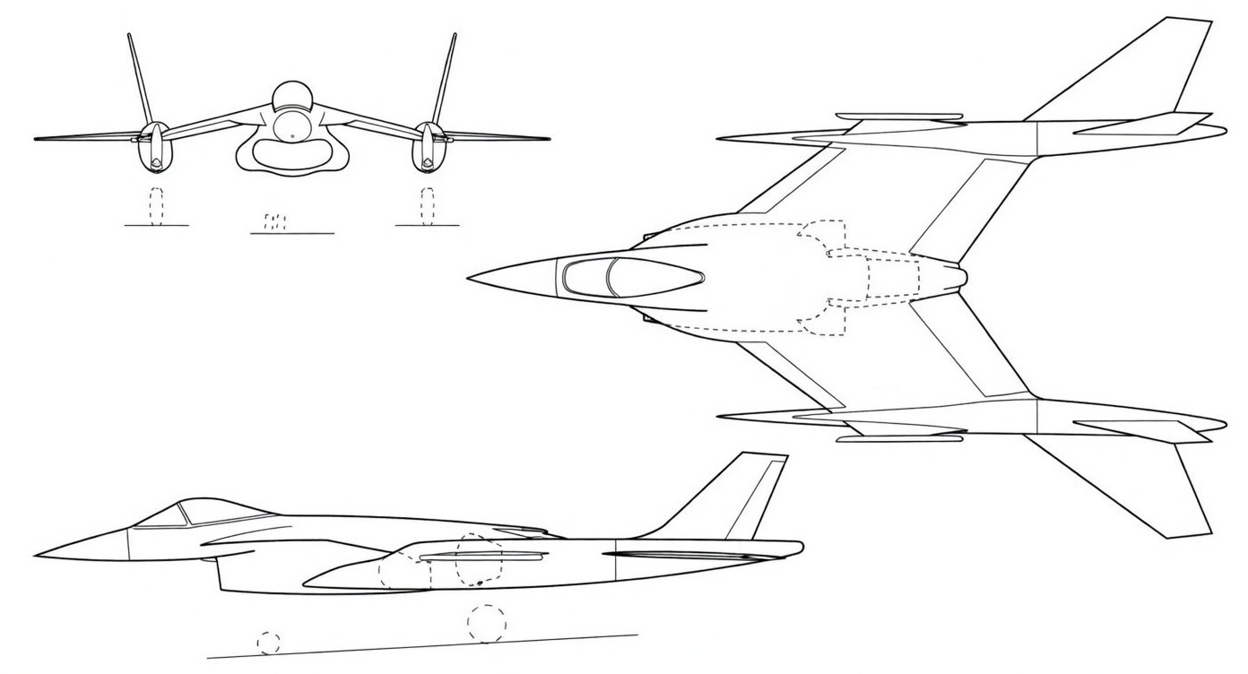
A schematic diagram of the British Aerospace P.1219 fighter jet. The external tail unit was a distinctive feature of the P.1219 family of designs developed by British Aerospace in 1982. However, the purpose of these design studies was to explore methods for reducing weight, rather than to implement advanced aerodynamic concepts. Illustration by Guy Inchbold © 2022. Image processed by lmarena.ai
источник: Guy Inchbald «Outside edge» «The Aviation Historian» №38, pages 106-118
Translation first published at — https://vk.com/@710541705-outside-edge-03