The Forgotten Giants of the Sky: Fairey’s Passenger Airliner Designs from the Late 1930s to the Late 1940s. Part 1

Contents:
Editor’s Foreword: By the mid-1930s, chaos reigned in the world of British civil aviation: outdated biplane airliners struggled to cover routes across the empire, while the Americans were producing and actively using fast and efficient all-metal monoplanes. Drawing on original documents, Fairey expert Bill Harrison examines the company’s response: the ambitious but ultimately unrealized FC series—a range of prewar and postwar passenger airliner designs.
In the late 1960s, Charles W. Kane, founder of the nonprofit organization Air-Britain, called me and asked if I had a letter from Clarence “Kelly” Johnson, chief designer at Lockheed, in which Johnson acknowledged that he had incorporated some of the ideas proposed for the Fairey FC.1 airliner into the design of the American L-049 Constellation passenger aircraft. Charles Kane said he had such a letter but couldn’t find it, and asked if I might have sent it to him, as the organization’s expert on the Fairey company. Unfortunately, I have not seen such a letter. However, there is a certain similarity between these two aircraft: work on the FC.1 began in 1938, and on the Constellation project the following year. I subsequently wrote to Johnson, who replied that he hadn’t used any ideas from the FC.1 project—well, what else could he have said, right?
So, let the saga begin …
Kadman’s Report
In November 1937, a committee was established in the United Kingdom, chaired by Lord John Cadman, to examine the state of British civil aviation, as well as to investigate allegations of inefficiency within the Ministry of Aviation and personnel issues at Imperial Airways. The committee’s report concluded with an urgent call for the use of government funding to develop and manufacture commercially viable aircraft capable of competing on the international stage. The report, published on March 8, 1938, was preceded by 13 pages of introductory “remarks” from the government, one of which pointed out that British aircraft manufacturers, having received lucrative military orders and contracts as part of the Royal Air Force’s expansion programs, had shown little willingness to undertake costly projects for the production of civil aircraft, work on which would likely have to be halted once hostilities began. This was prompted by concerns raised by the Civil Aviation Authority and the Ministry of Aviation that the United Kingdom was falling behind in the development of land-based civil aircraft. To address this issue, the report proposed that the Ministry of Aviation, in collaboration with aircraft manufacturers and commercial airline operators, define a set of requirements and solicit design proposals, from which the most promising would be selected for further production.
The report also recommended increasing government support and funding for civil aviation, suggesting that a lack of funding is what is holding back the United Kingdom’s ability to develop competitive, modern passenger aircraft. The report went on to state that the government could provide greater assistance to civil aviation and that a specialized department headed by a deputy minister should be established. The report went on to state that Imperial Airways should focus on routes to the colonies and dominions of the British Empire, while British Airways Ltd, using British-manufactured aircraft, should operate flights to major cities on the European continent. In addition, British Airways Ltd should immediately apply for government subsidies to launch routes to the Caribbean, the Pacific region, and South America. The report also noted the need for closer cooperation between civil and military aviation and for additional research.
Taking the report into account, the government established the Directorate of Civil Research & Production (DCRP), which provided funding for two new passenger aircraft: the Short S.32 and the Fairey FC.1. Development of the former was already underway in response to the Ministry of Aviation’s technical specifications, which called for a long-range monoplane passenger aircraft to replace the Armstrong Whitworth Ensign airliner, which had already proven unsuitable for its intended tasks. Tests of the two competing designs were intended to determine which one would be selected for Imperial Airways.
Following Lord Cadman’s report, preliminary specification 15/38 was issued with remarkable speed for
“A 10- to 30-seat commercial passenger aircraft,”
which was sent on May 17, 1938, to Armstrong Whitworth, Bristol, Fairey, General Aircraft Ltd (GAL), and Vickers. The accompanying letter explained that financial assistance was available, including contributions toward prototype development and the manufacture of production tooling. The letter also requested estimated production rates, delivery schedules, and the amount of financial assistance required. One of the key conditions was that the work involved must not interfere with urgent military contracts. Applications to participate in the competition were to be submitted within seven weeks.
Vickers quickly declined the invitation, followed in July by Armstrong Whitworth. Bristol, Fairey, and GAL accepted the offer, as did Folland, which was later also invited to participate in the competition. In July, Specification 14/38 for a long-range passenger aircraft capable of transatlantic flights was issued and forwarded to Short Brothers.
Specification 15/38 called for the creation of
“a four-engine, all-metal, single-wing civil airliner”
With a gross weight of approximately 42,000 pounds (19,000 kg) and design features that ensure the cabin is pressurized, this is truly a radical solution by today’s standards. The aircraft was designed to be capable, with one engine out, of climbing 66 feet (20 m) after a 1,000-yard (914 m) takeoff run and flying 1,000 miles (1,610 km) in calm conditions on three engines operating at 70% of their rated power. The stall speed at maximum landing weight was not to exceed 68 miles per hour (109 km/h). The aircraft was to be equipped with an autopilot and an anti-icing system. The aircraft’s approach characteristics were to comply with an instrument approach using the Lorenz system.
It is not surprising that the designs submitted by the four aircraft manufacturers were similar in outline. On July 4, 1938, Fairey submitted its proposals and drawings for an attractive aircraft design with a wingspan of 105 feet (32 m), a length of 76 feet (23.2 m), and a height from the tip of the rudder of 22 feet 6 inches (6.85 m). The horizontal tailplane span was 30 feet 6 inches (9.3 meters). With a gross weight of 45,218 pounds (20,500 kg), the aircraft was expected to reach a cruising speed of 275 miles per hour (443 km/h) at an altitude of 11,000 feet (3,350 m), with a range of 1,850 miles (2,965 km). It was designed to carry 1,600 gallons (7,273 liters) of fuel and have a service ceiling of 25,000 feet (7,620 m). These figures were based on the conclusions of Robert T. Youngman, head of the technical department at Fairey.
The new aircraft was to be equipped with the yet-to-be-tested Rolls-Royce Exe 24-cylinder air-cooled X-shaped engines, which produced 1,200 l.s. at 4,000 revolutions per minute. This engine was a serious contender, as it was also being considered as the powerplant for the Fairey Barracuda torpedo bomber for the Royal Navy’s Fleet Air Arm (FAA). When work on the Exe engine was suspended in the summer of 1939, the 1,000-l.s. Bristol Taurus valveless engine was selected as the alternative powerplant for the new passenger liner, and it was this engine that appeared in most of the company’s promotional brochures.
Other engine options considered included the Bristol Hercules, the Wright GR-1820-G102A Cyclone with NACA cowlings, the Wright F.62 (the preferred choice of British Airways), and the Wright G.100. The propeller blades were to be equipped with lubrication rings [a tubular ring around the propeller hub through which an antifreeze solution is distributed to the propeller blades by centrifugal force—Ed. note] and arranged in a staggered pattern so that ice thrown off the blades would not strike other blades of the aircraft. The landing gear was a tricycle configuration with a nose gear. The main landing gear legs retracted by rotating toward the aircraft’s centerline from recesses located at the wing roots, while the nose gear retracted by rotating backward into a recess beneath the cockpit. To prevent damage to the rear of the fuselage in the event of excessive nose-up pitch during takeoff, it was planned to install a small tail wheel.
The total payload of the new passenger aircraft was approximately 10,100 pounds (4,980 kg), which, combined with the aircraft’s total weight of 37,930 pounds (1,200 kg), exceeded the original specification requirement of 42,000 pounds (19,050 kg). The aircraft’s design included pressurization, allowing the airliner to cruise at an altitude of 15,000 feet (4,600 m). This could be achieved by installing compressors on two of the four Taurus engines, with each compressor providing twice the required air volume. Thus, the loss of a single engine would not be critical to maintaining pressurization. The new long-range airliner was expected to be completed in 1940.
Economic Aspects
Despite numerous changes to the financial proposals submitted, Fairey estimated the short-term cost of developing a new type of airframe at 120,000–140,000 pounds sterling, plus the cost of the powerplants; with a production run of 100 aircraft, the price was to be reduced to 50,000–60,000 pounds sterling, plus the cost of the powerplants. According to information obtained by a data-gathering delegation from the Ministry of Aviation, the Douglas DC-4 was offered at 78,000 pounds per aircraft for an order of 20 units; Boeing offered its Model 307 at 68,000 pounds; the Junkers Ju 90 cost 50,000 pounds sterling, and the Focke-Wulf Fw 200 Condor could be purchased for 40,000 pounds sterling. The difference was negligible. Of the total sum of 375,000 pounds allocated for the development of civil aircraft in 1938, 80,000 pounds sterling had been provisionally allocated toward the unit cost of the selected aircraft, developed in accordance with Specification 15/38.
In August 1938, the new directorate—whose establishment had been recommended by the Cadman Committee— — the Directorate of Civil Aviation & Production, headed by Sir Francis Shelmerdine and the new head of the DCRP, Major C.J. Stewart (Maj C.J. Stewart)—conducted a technical evaluation of four designs developed under Specification 15/38. To simplify the evaluation, Shelmerdine and Stewart analyzed the four designs by presenting each “on paper” with Bristol Taurus engines, a tricycle landing gear, and identical fuel capacity. As expected, the performance characteristics and weights were similar for all four designs, but the GAL.40 design came out on top in terms of overall technical merits. However, these were merely “paper planes,” and Shelmerdin and Stewart were very interested in bringing Fairey into the production of civil aircraft. Furthermore, at the first selection meeting held on August 9, 1938, British Airways Managing Director Alan Campbell-Orde (Alan Campbell-Orde), made it perfectly clear that it would be difficult for his airline to place any orders with anyone other than a large and experienced aircraft manufacturer.
The Ministry of Aviation asked four competing aircraft manufacturers whether they were prepared to begin production of 20 aircraft if all costs associated with the creation and development of the prototype were covered by the government, and, if not, whether they would be willing to do so if the costs of production tooling and fixtures were also covered. Fairey responded that they would agree to the proposal if the prototype costs were covered based on an initial production run of 20 aircraft. Fairey estimated that a total of 1,638,000 pounds sterling would be required, of which 160,000 pounds sterling would be paid for the development of the prototype, and 73,900 pounds sterling for each of the 20 production aircraft.
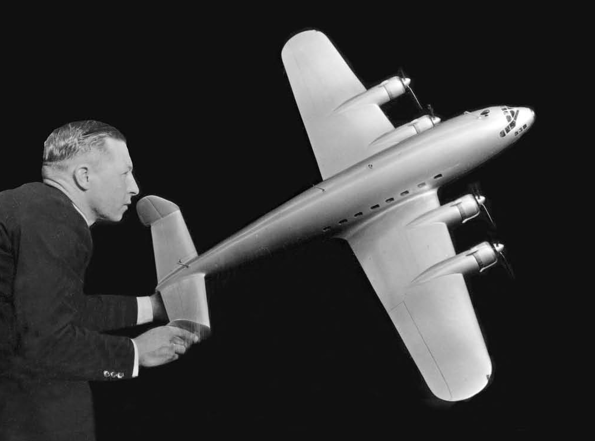
John W.R. Taylor (John W.R. Taylor), who worked for the company early in his career and later became one of the most prominent aviation writers in the United Kingdom. The model shown in the photograph of the Fairey FC.1 passenger aircraft—which was ultra-modern for its time—is depicted without the central keel, which was added at a later stage. The photograph is courtesy of the author of the article
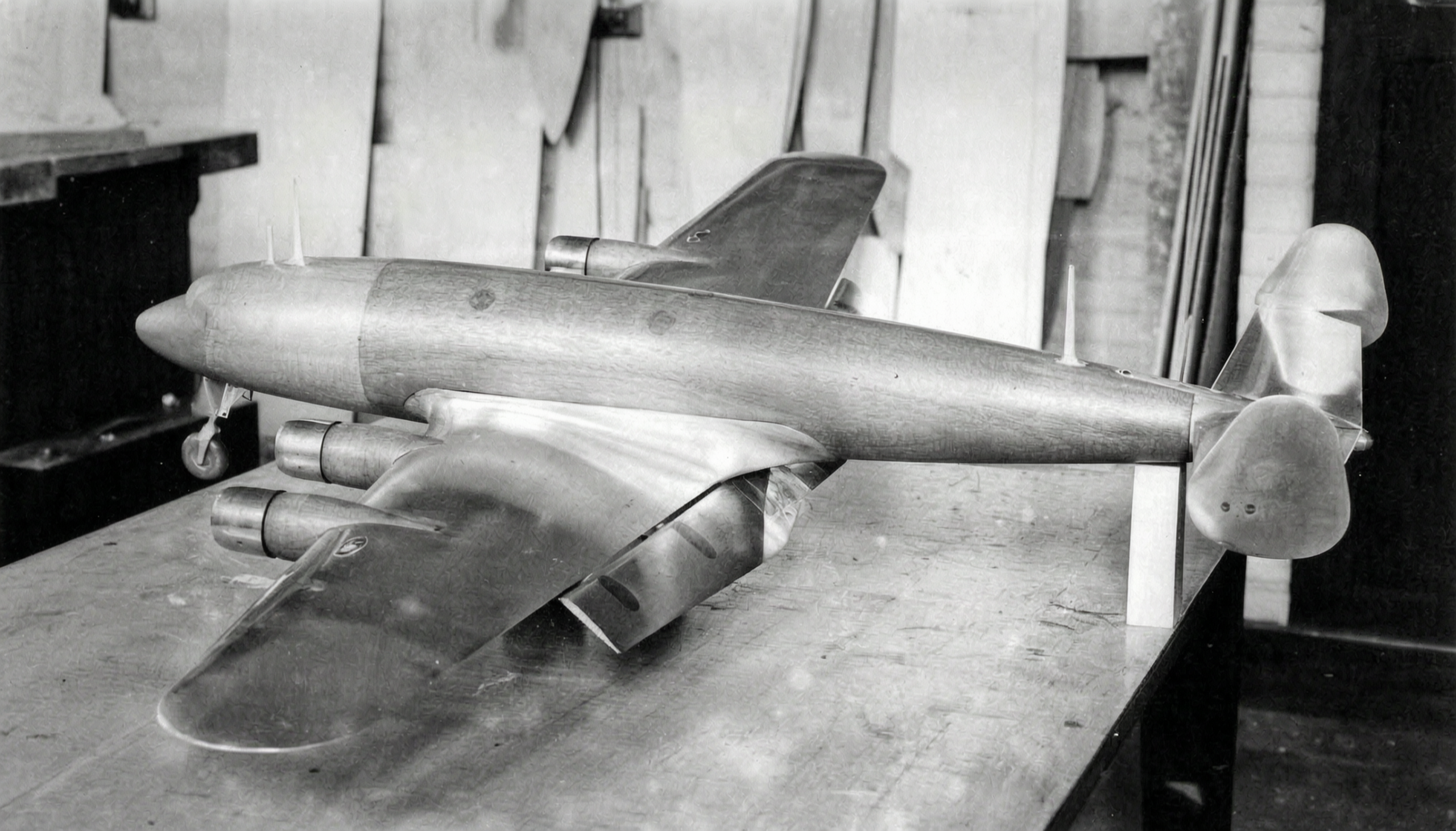
This beautiful, handcrafted, full-scale model of the Fairey FC.1 passenger aircraft prototype was used in wind tunnel tests. The model shown in the photo features extended Fairey-Youngman flaps and still has a twin-tail configuration. Photo from the collection of Philip Jarrett. The image was processed by lmarena.ai
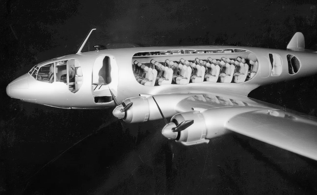
The company’s model of the Fairey FC.1 passenger aircraft project featured cutaway sections showing the airliner’s proposed interior layout. Passengers were to be seated in several rows, each consisting of two seats on either side of the center aisle, with overhead compartments for carry-on luggage. The radio operator was to be stationed in the cockpit to the right of the co-pilot’s seat. The photograph was provided by the author of the article. The image was processed by lmarena.ai.
And now, about what was getting in the way of the work. It had been agreed that two prototypes would be needed, but British Airways, which was participating in technical negotiations regarding the specifications at the time, stated that the company required only 12 such aircraft—significantly fewer than the 20 originally planned. In addition, the airline’s management stated that it was unable to place an order and that the FC.1 was not suitable for its longer routes. However, on November 12, 1938, following approval from the Treasury, Fairey accepted the proposal and agreed to begin manufacturing the Fairey Commercial No. 1 (FC.1). A total of 225,000 pounds sterling was allocated for the production of two prototypes, plus 80,000 pounds sterling for each subsequent aircraft, as well as production tooling; Fourteen FC.1 aircraft were ordered—the revised number was provided by British Airways.
Production begins … and ends
Fairey immediately set to work, creating an excellent full-scale mockup made of wood and fabric, which was shown to the aviation press in early 1939. The company’s founder, Richard (later Sir Richard) Fairey, also saw other potential uses for the FC.1, one of which was the FC.1M military transport aircraft, which could be produced alongside the passenger version. Richard Fairy personally believed that the British armed forces urgently needed a modern transport aircraft capable of moving troops around the world. However, he did not take into account the prevailing opinion of the time or the views of the ministers, who could not understand how a civilian passenger aircraft could simultaneously serve as a military transport. The Secretary of State for Aviation, Sir Kingsley Wood, personally replied to Richard Fairie, stating that it was impossible to convert a civilian airliner into a military transport aircraft.
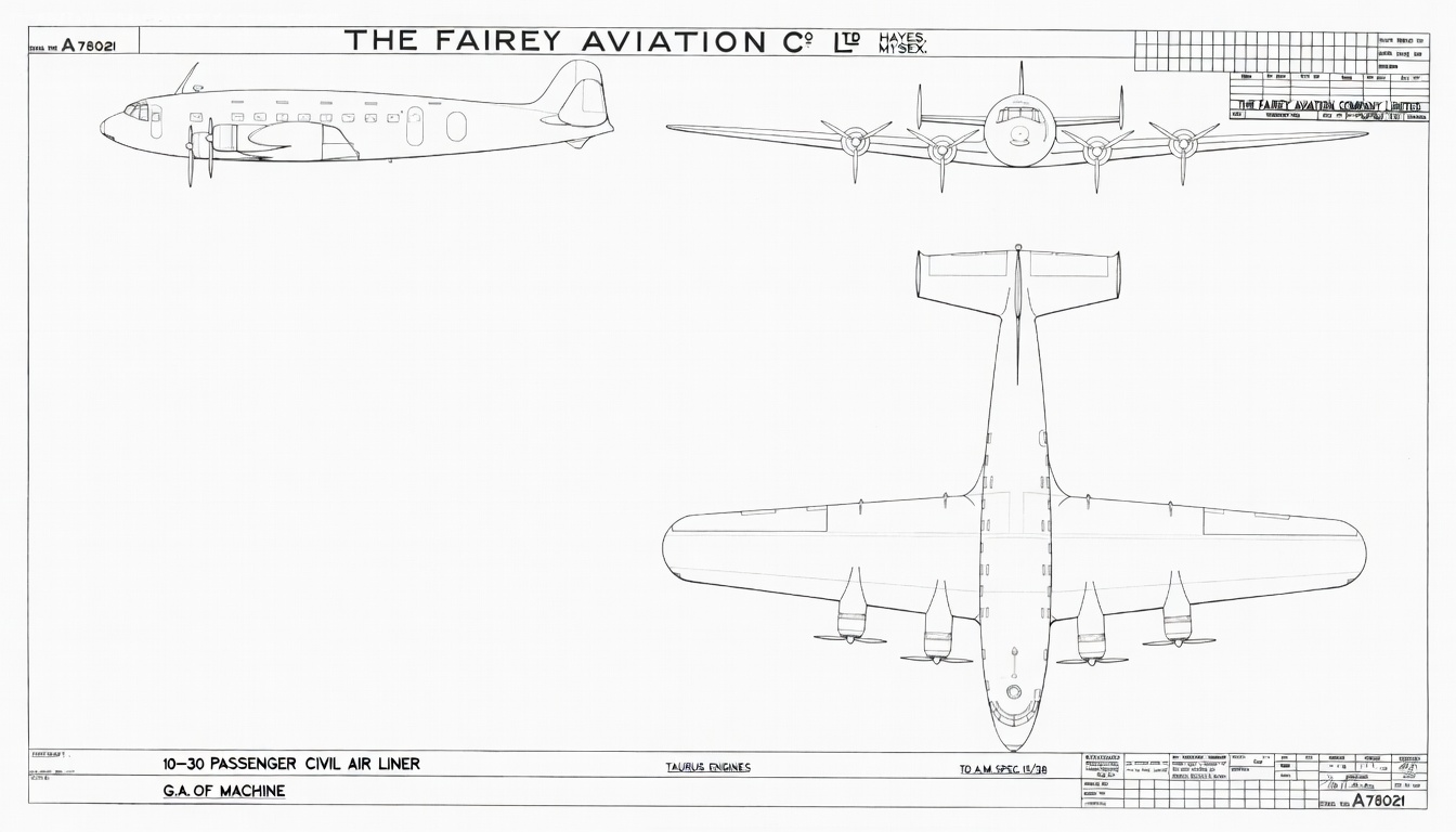
An original general arrangement drawing of the Fairey FC.1 passenger aircraft, powered by Bristol Taurus engines, developed in response to Specification 15/38 issued by the Ministry of Aviation on July 1, 1938. Initially, Exe X-shaped inline valveless engines were selected as the powerplant for the FC.1, but Rolls-Royce suspended their development to focus on the production of Merlin engines. The drawing is provided by the author of the article. The image was processed by lmarena.ai
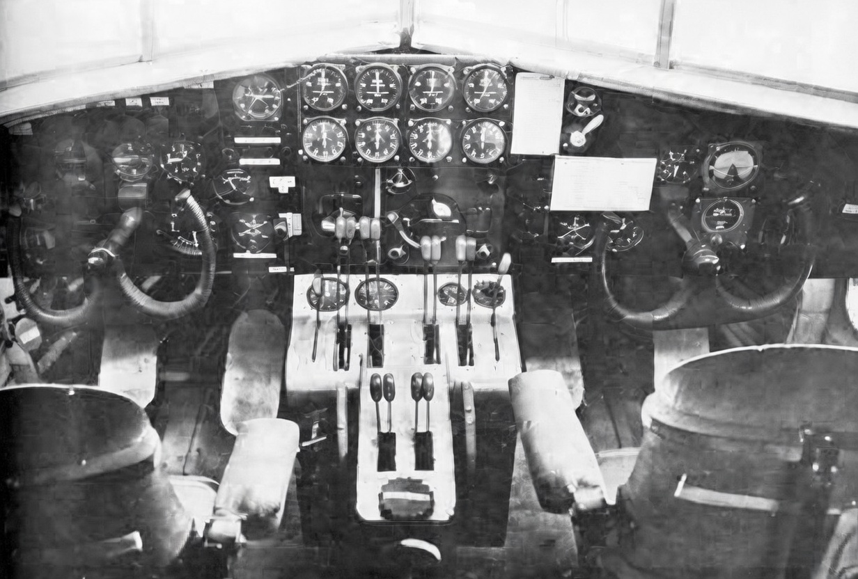
The instrument panel of a full-scale mock-up of the Fairey FC.1 passenger aircraft, with a Sperry autopilot panel mounted on it. Photo from Philip Jarrett’s collection. The image was processed by lmarena.ai
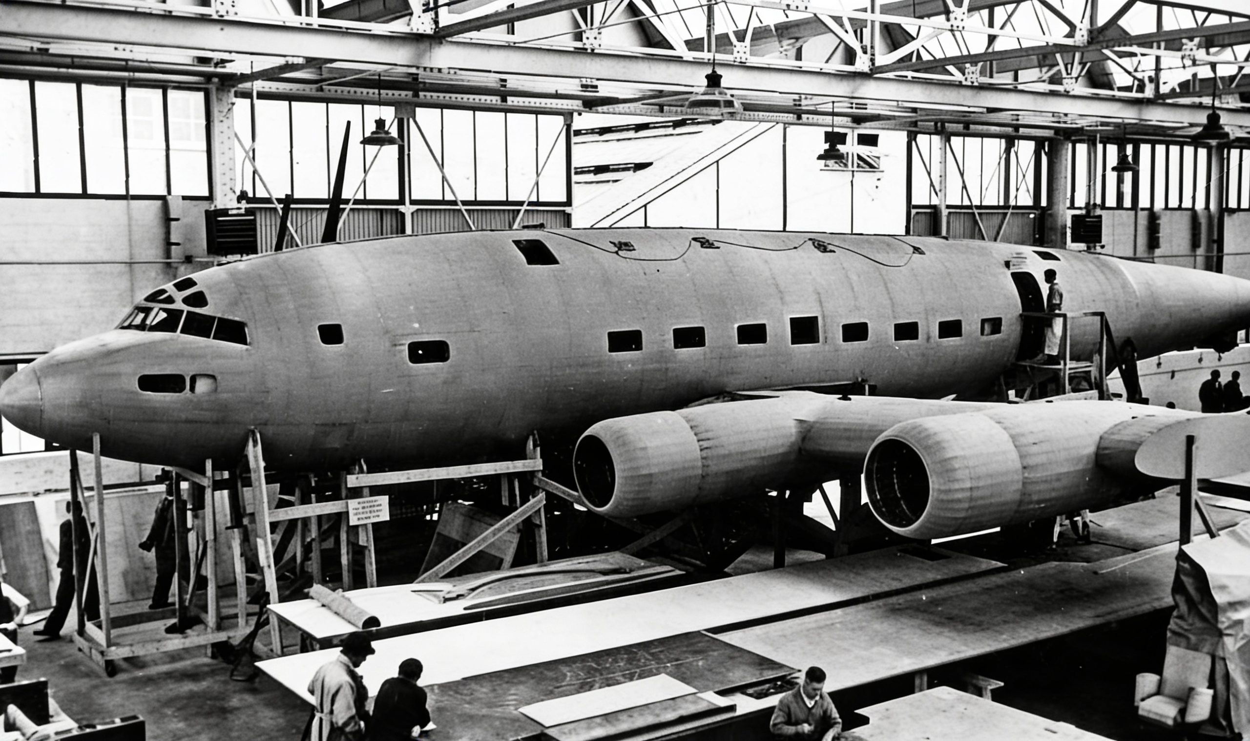
By the spring of 1939, construction of a full-scale model of the Fairey FC.1 passenger aircraft in the factory’s experimental workshop in Heys was nearing completion. Photo from the Philip Jarrett collection. The image was processed by lmarena.ai
Fairey then presented the FC.1 variant—which featured larger dimensions and a longer range—to Sir Francis Shelmerdin, head of the Civil Aviation and Manufacturing Authority. With a set of working drawings available, the transition to a larger version would have been relatively simple and, moreover, would have perfectly met the Royal Air Force’s requirements worldwide. Richard Fairey was shocked when, on October 17, 1939, Sir Francis Shelmerdin canceled the FC.1 program, and in May 1940, production of the prototype was completely halted. Fairey was instructed to completely convert its civil aircraft assembly shop and, for the duration of the war, to store all finished parts and tooling in a warehouse at the rear of the plant.
Consequently, development of a highly promising British airliner was halted, which dealt a severe blow to the United Kingdom’s civil aviation industry. Sent to Washington as a member of the aviation section of the British Procurement Commission, Richard Fairie was deeply disappointed to see how the Americans were transforming four-engine aircraft with tricycle landing gear, such as the DC-4 and the Constellation, into world-class military transport aircraft. Nevertheless, he sent instructions back to the UK for his own company to keep the FC.1 program documents on hand. The company complied with this directive, and by the end of 1945, the FC.1 had been redesigned and fitted with four valveless Bristol Hercules engines. However, work on the FC.1 program was never resumed.
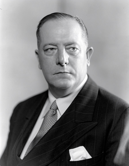
in October 1939, following the painful cancellation of the FC project.1 Richard Fairy was selected to work in the aviation section of the British Procurement Commission, which required a respected figure with extensive practical and managerial experience to coordinate design, development, and production procedures between the United Kingdom and the United States. He did not return to the United Kingdom until after the war. Photo courtesy of the author. The image was processed by lmarena.ai.
So, what would this elegant, cutting-edge aircraft look like, and how was it supposed to be built?
Brief Technical Description
The FC.1 fuselage was to consist of three detachable sections, each of which had a monocoque structure and was made of lightweight aluminum alloys (Alclad). The forward section extended from the nose to the bulkhead at the front of the passenger cabin and included the flight crew cockpit, workstations for the flight engineer and radio operator, the forward cargo compartment, and a crew restroom. The radio operator, seated behind the co-pilot, was responsible for operating the short- and medium-wave transmitters and receivers, the medium-wave direction-finding receiver with a frame antenna, and the VHF equipment for the approach and landing.
The central section consisted of the passenger cabin, and the space between the cabin floor and the outer skin was used as an additional cargo compartment. The passenger cabin was 30 feet 6 inches (9.3 m) long and accommodated rows of double seats with a total width of 4 feet (1.2 m) on either side of the center aisle. There were eight windows on each side; every other window served as an emergency exit and could be pushed out. The height above sea level was to be 6 feet 6 inches (2.0 m), and the space per passenger was to be at least 60 cubic feet 3 (1.7 m³). The fuselage was to have a circular cross-section, which would allow the aircraft to be equipped with a pressurized cabin in the future.
The rear section of the fuselage extended from the rear bulkhead of the passenger cabin to the tail and included a rear cargo compartment with access through it to facilitate maintenance. Baggage and cargo were to be transported in cargo compartments with volumes of 150 cubic feet (4.3 m³) and 160 cubic feet (4.5 m³); there was also additional storage space under the passenger compartment floor with a volume of 200 cubic feet (5.7 m³). The de-icing fluid tank was to be located in the upper right portion of the rear section.
The twin-spar wing had an all-metal structure with a load-bearing skin, and each wing spar consisted of inner and outer sections. The inner part of the wing spar carried the flaps and engine nacelles, with the latter designed to be autonomous, interchangeable units based on the “power egg” principle (a power egg is an airship nacelle). The main fuel tanks, with a capacity of 1,800 gallons (8,172 liters), were to be installed inside the wing spar; two tanks were located between the spars and one at the leading edge, and all of them could be easily removed for maintenance. The rear section of the wing, along with the flaps, was designed to detach easily from the rear spar.
The outer sections of the wing consoles were constructed with watertight joints so that, in the event of a water landing, these sections could function as buoyancy chambers. The ailerons had a metal structural framework consisting of spars and ribs, with fabric covering. The Fairey-Youngman flaps, equipped with a hydraulic drive, were of all-metal construction. The hydraulic pump was powered by the engine, although there was also a hand pump in the cockpit for emergency use. These flaps were designed to provide high lift with low drag. The flaps were controlled by an ingenious system of linkages that allowed them to be extended from the stowed position to a position beneath the rear of the wing, creating an additional aerodynamic profile comprising approximately one-third of the wing’s chord. During takeoff, this provided high lift without significantly affecting the lift-to-drag ratio. With the flaps extended to a zero angle of attack, the lift-to-drag ratio and takeoff distance were reduced by approximately 20%. During landing, the flaps were set to 30°, which provided a glide angle suitable for an instrument approach using a radio beacon system.
The vertical tail consisted of three fins and rudders, which provided excellent course control and good anti-spin characteristics. The cantilever stabilizer had an all-metal structure made of lightweight alloys and a functional skin. The angles of attack of the stabilizer and fins were not adjustable, but the elevators and rudders were equipped with trimmers controlled by the pilot. The elevators and rudders, like the ailerons, had an all-metal structural framework with spars and ribs and a fabric covering. Overall, the FC.1 was a well-thought-out design that incorporated many of the most advanced technologies of the time.
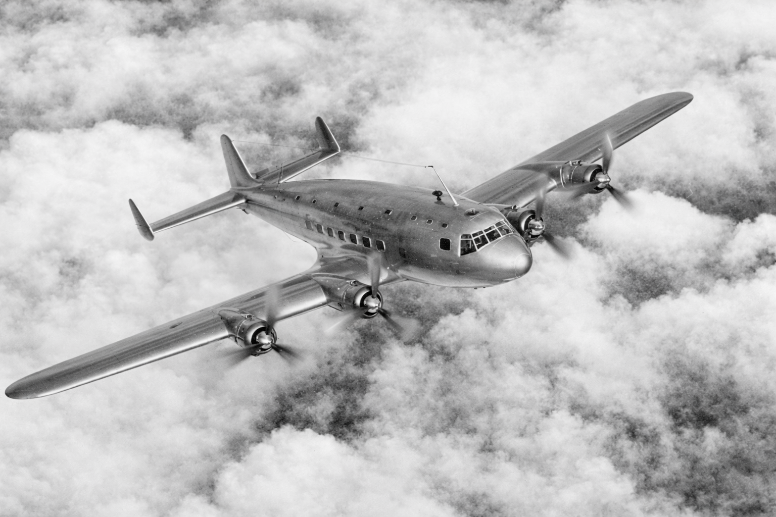
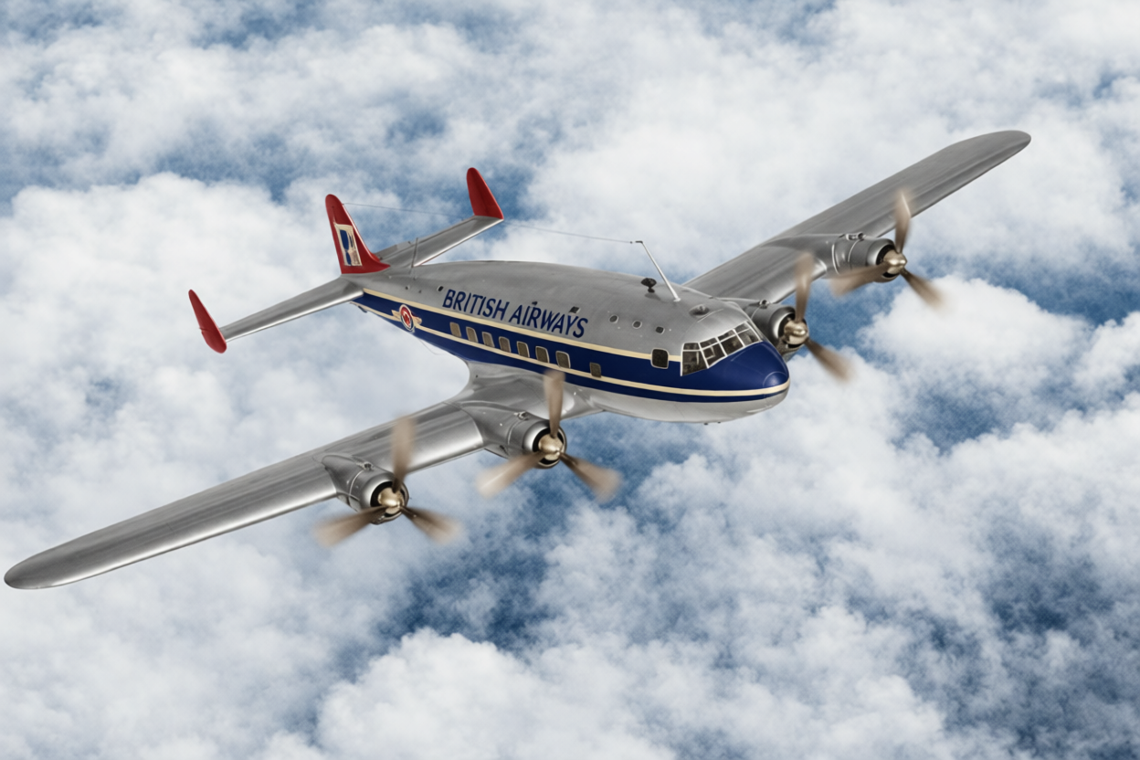
A promotional photomontage of a Fairey FC.1 passenger aircraft in flight against a typical cloudy backdrop. At this stage, the airliner already has a central stabilizer but still features tall cockpit windshield panels. By the time work on the model began, a more streamlined windshield design with lower panels had been developed. The photograph was provided by the author of the article. The image was processed by lmarena.ai.
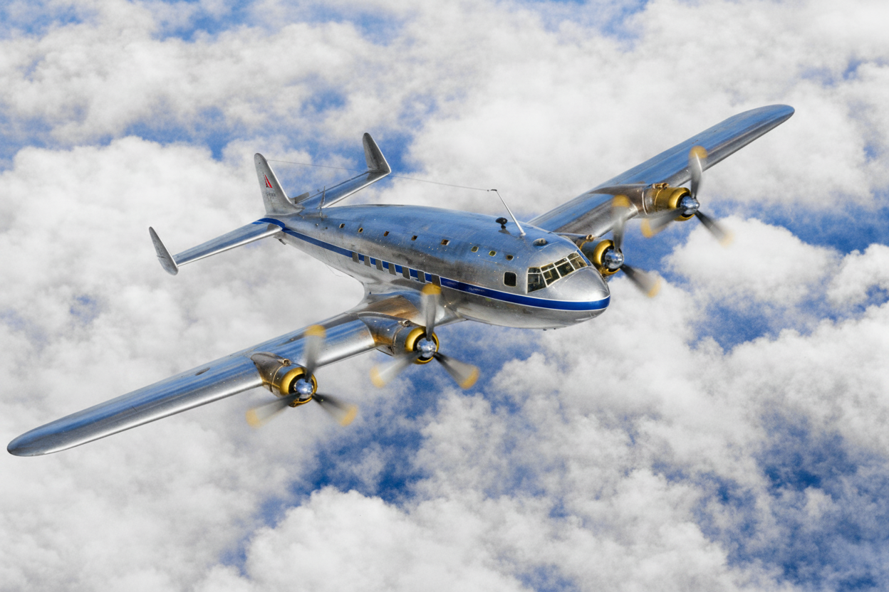
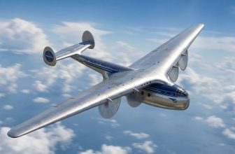
This is what a Fairey FC.1 passenger aircraft might have looked like when it entered service. The image was generated by lmarena.ai.
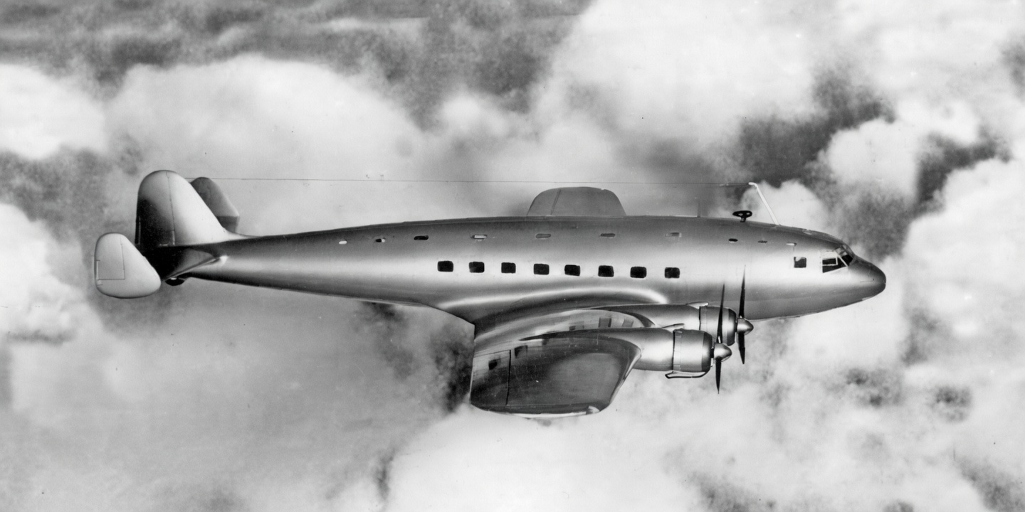
Another photomontage of a “flying” Fairey FC.1 passenger aircraft, which looks like a cross between the sleek de Havilland Albatross airliner—which first took to the skies in May 1937— and the American Lockheed Constellation passenger aircraft with a triple-fin tail, whose development did not begin until 1939 and which made its first flight in January 1943. The image is provided by the author of the article. The image was processed by lmarena.ai
источник: B.Harrison «Fairey’s commercial break» «The Aviation Historian» Issue No 21, Pages 96-108
Translation first published at – https://vk.com/@710541705-fairey-s-commercial-break-01