The Forgotten Giants of the Sky: Fairey’s Passenger Airliner Designs from the Late 1930s to the Late 1940s. Part 2

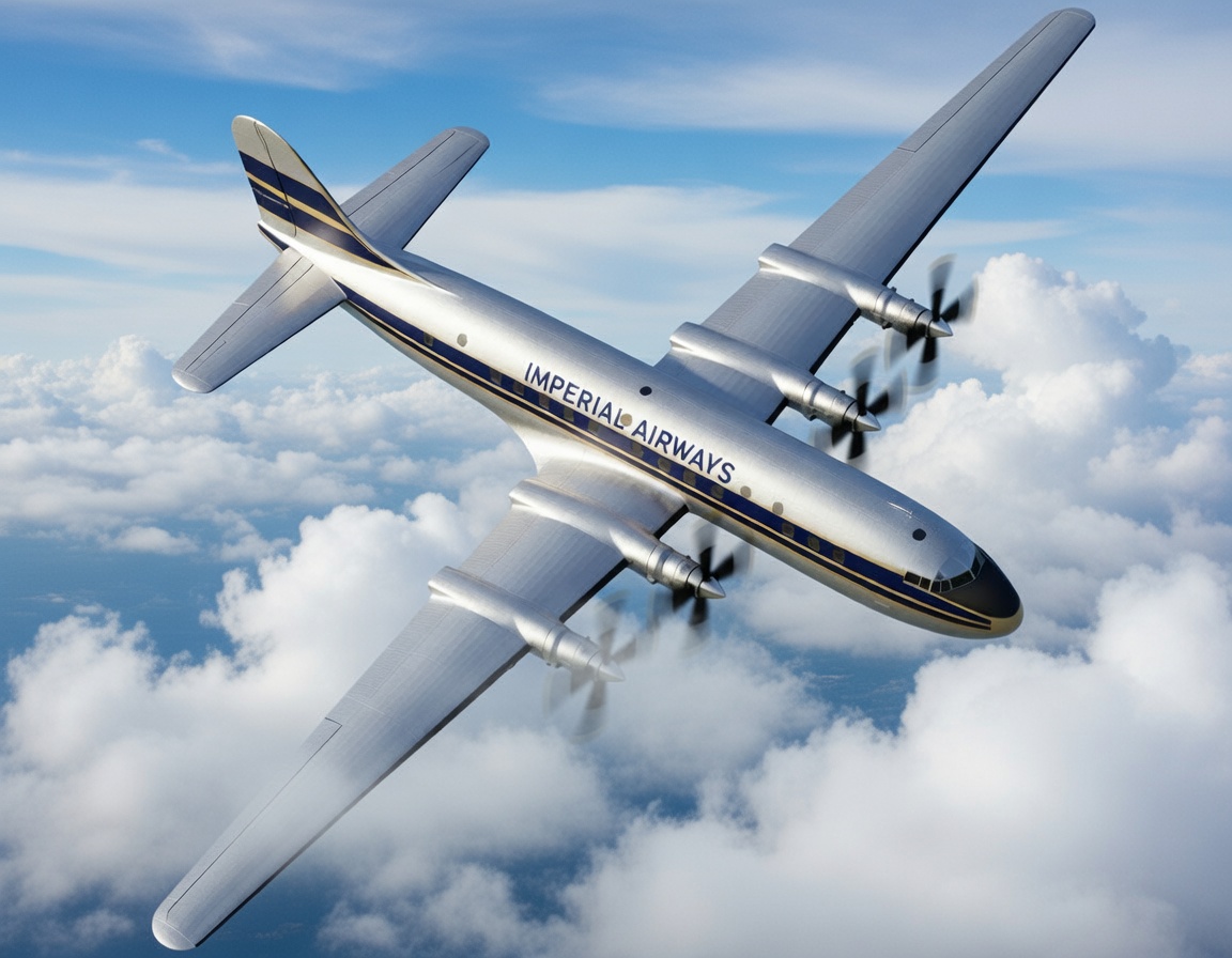
A postwar opportunity?
As the end of the war in Europe drew near, Fairey once again began to take an interest in building civilian aircraft. During the war, Fairey’s conceptual design team periodically conducted design work on airliners. The goal of this work was to create an attractive design with performance characteristics that would make the aircraft commercially successful. In this regard, they were guided by the work of various new committees, including the Brabazon Committee, established in late 1942 to develop a strategy for the postwar development of civil aviation in the United Kingdom, part of which was to include the preparation of
“general technical specifications for several types of aircraft required for postwar air transport.”
It is important to note that part of the committee’s work involved examining which civilian aircraft would be best suited for conversion into military transport aircraft. This served as official confirmation of Richard Fairi’s position, which he had expressed four years earlier.
In the postwar period, Fairey began studying general trends in the passenger aircraft market and concluded that, in the medium-sized passenger aircraft category, market demand would be met by a 30-seat aircraft weighing approximately 40,000 pounds (18,100 kg). Based on engine availability, the 1,610-horsepower Rolls-Royce Merlin T.24-2 engines were selected as the preferred powerplant, while Bristol engines were chosen as a backup option. For the American and global markets, the plan was to install Wright Cyclone engines, although it was also recognized that within a few years, piston engines would give way to gas turbine (turboprop) engines and that, for this reason, radical design changes should be kept to a minimum.
Fairey’s initial preliminary design called for the installation of three Merlin engines: one in each wing and one in the nose of the fuselage, with each engine’s nacelle featuring a rubber-insulated structure. The propellers of the wing-mounted engines were to be positioned opposite the “soundproofed” section of the passenger cabin, which, with additional sound insulation, would have reduced noise and vibration levels. Fairey also proposed that a 30-seat airliner with a gross weight of approximately 42,000 pounds (19,000 kg), equipped with three interchangeable Merlin engines, would be Stage I (Stage I), to be followed by Stage II or the FC.3—as the project was later named—a passenger aircraft powered by two Armstrong Siddeley Double Mamba turboprop engines. Fairey estimated that, if approved, the first prototype would be ready within 22 to 26 months.
The Stage I (FC.2) project was an attractive light-alloy monoplane with a pressurized passenger cabin, a low-mounted wing, and a tricycle landing gear configuration with a nose gear. The aircraft was designed to achieve the lowest possible weight while carrying the maximum payload and to ensure optimal maneuverability and the safest possible takeoff and landing characteristics. With passengers seated three to a row, there was to be sufficient space for them in the cabin, with 53 cubic feet (1.6 m³) per passenger. The compartment for luggage and other light cargo was located on the right side of the cockpit behind the navigator’s station, with a loading door built into the front of the fuselage. Additional cargo space was also planned to be allocated beneath the floor of the passenger cabin.
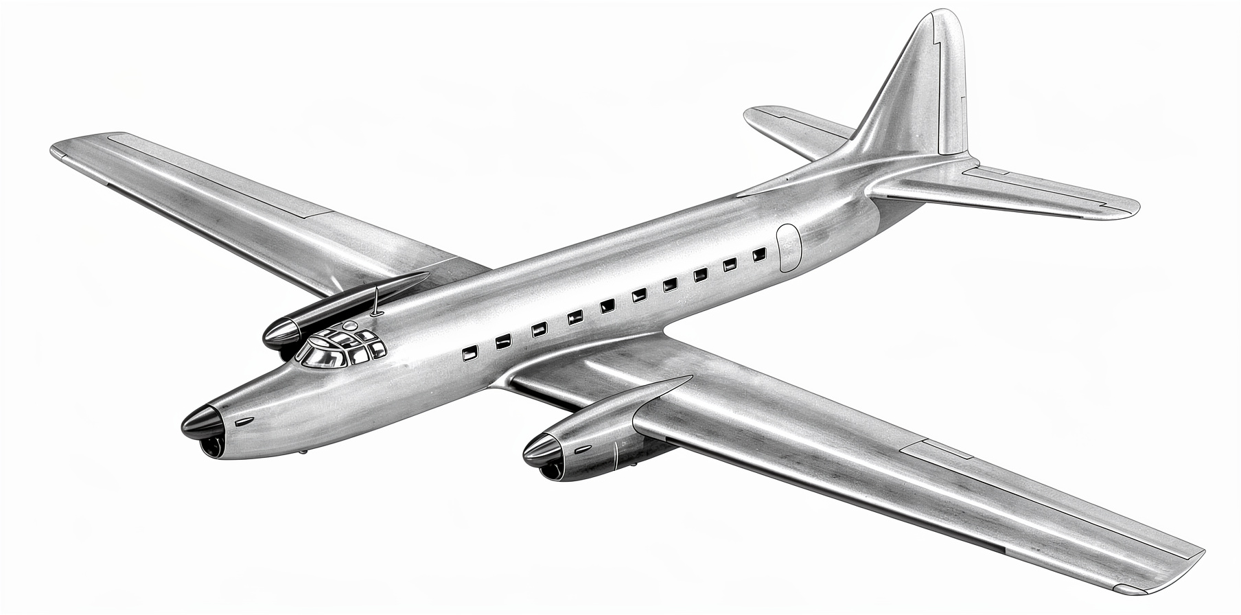
An official illustration by Fairey depicting its first postwar airliner project, the FC.2, which was to be powered by three Rolls-Royce Merlin T.24 engines. This was the first stage of development; eventually, the three-engine configuration would be replaced by a pair of turboprop engines mounted on the wing pylons. The illustration is provided by the author of this article. The image was processed by lmarena.ai.
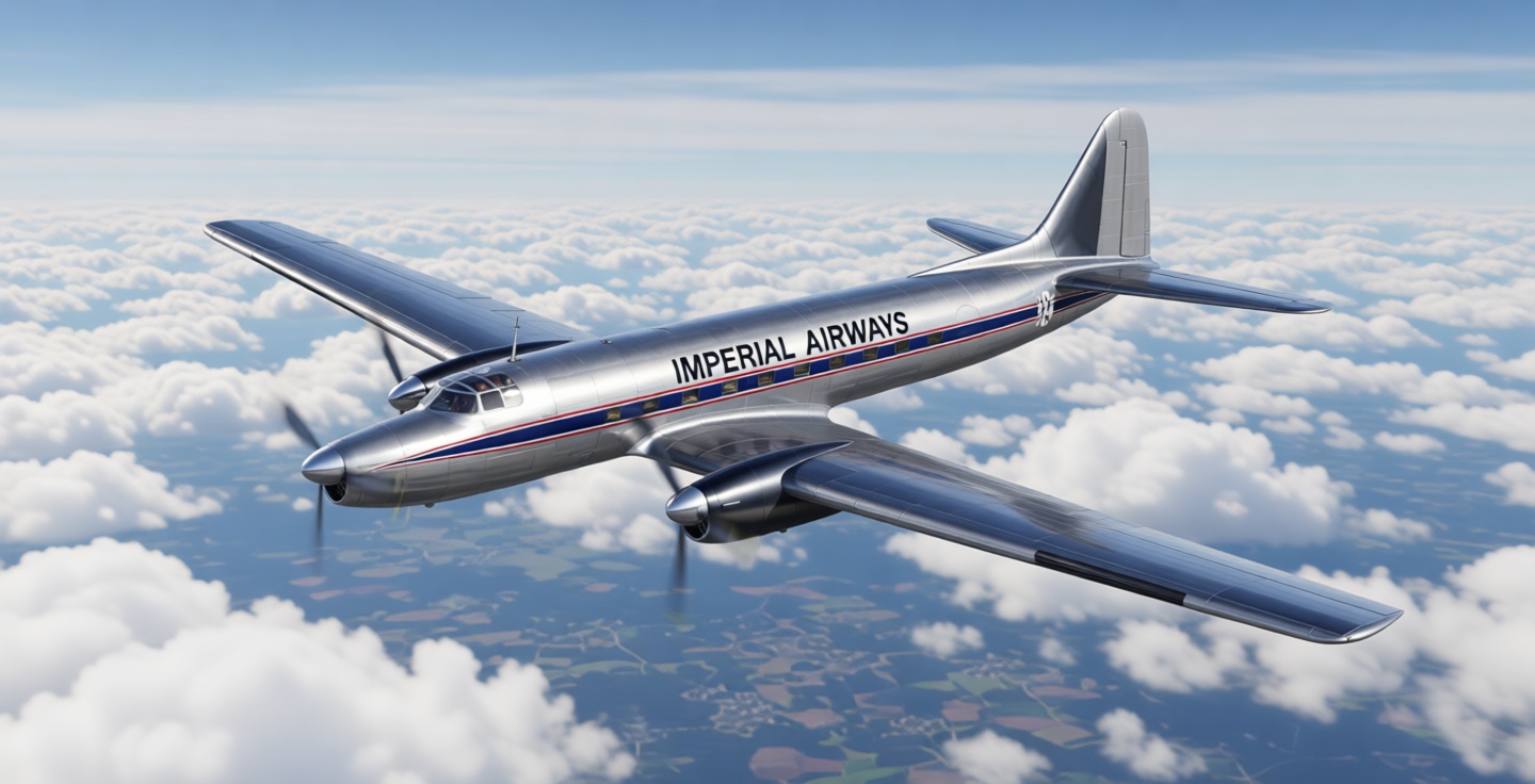
This is what a Fairey FC.2 passenger aircraft might have looked like when it entered service. The image was generated by lmarena.ai.
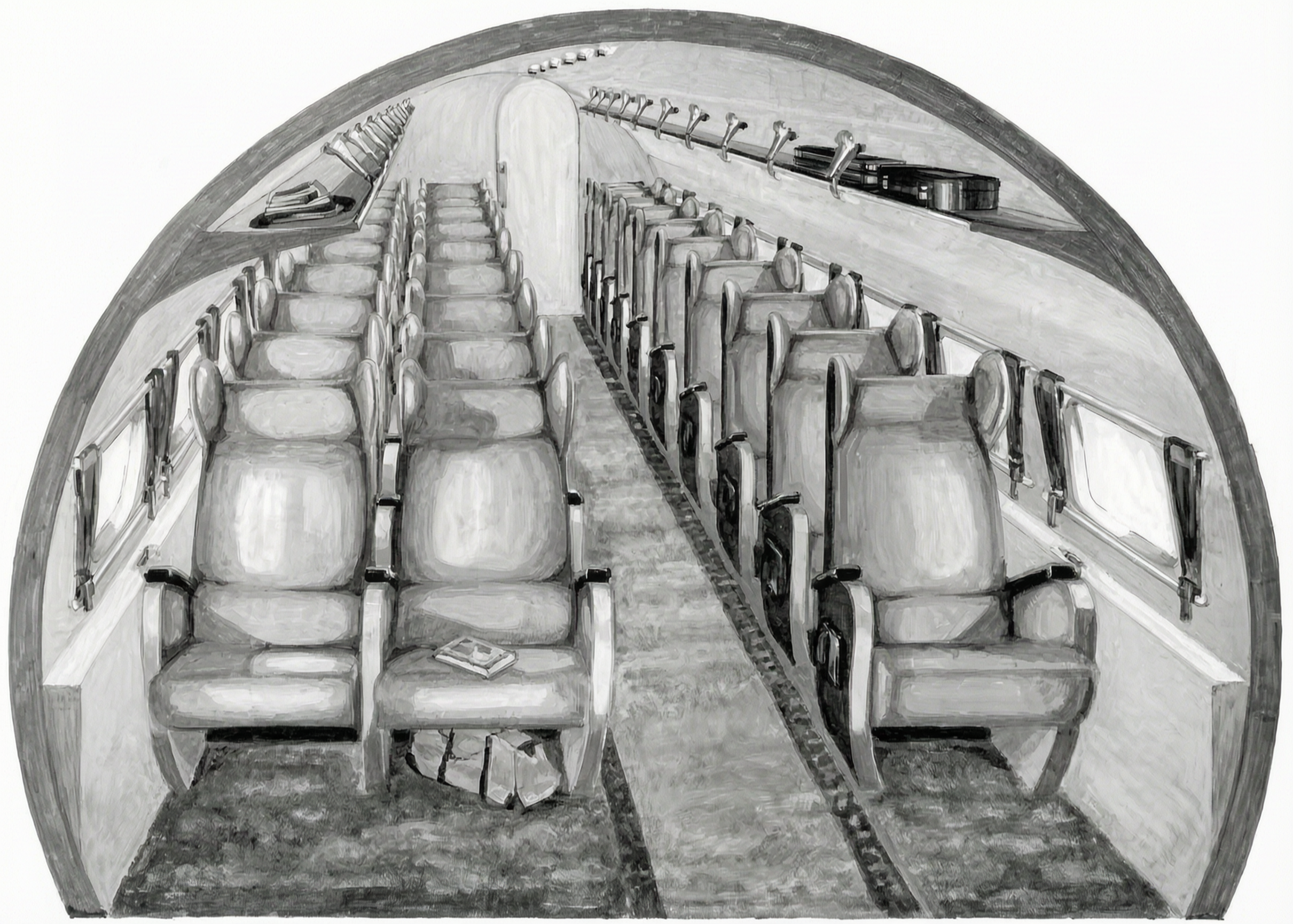
The proposed passenger cabin layout for the FC.2 airliner project called for rows of two-seat configurations on the right side and single seats on the left side, separated by a central aisle. The Merlin T.24 was a specialized version of the Merlin Mk 24 engine equipped with a two-stage supercharger, developed to extend service life and for installation on the Royal Air Force Transport Command’s Lancaster, Lancastrian, and York aircraft. The illustration is provided by the author of the article. The image was processed by lmarena.ai
Two versions of the FC.2 project were proposed: the first with an unpressurized cabin for low-altitude, shorter routes, and the second with a pressurized passenger cabin for flights on high-altitude routes. In the second version of the FC.2 project, air supply was to be provided by two Marshall superchargers powered by wing-mounted engines. The pressurization system was designed to maintain sea-level pressure in the passenger cabin up to an altitude of 12,500 feet (3,870 m), after which the cabin pressure would gradually change until reaching an altitude of 25,000 feet (7,600 m), at which point the cabin pressure would be maintained at the level of normal atmospheric pressure at an altitude of 8,000 feet (2,400 m).
The FC.2 airframe was to feature a fuselage made of lightweight alloys with a circular cross-section; the semi-monocoque fuselage was designed to combine simplicity of construction with ease of maintenance. The wing and tail were to have a traditional design, with two spars forming the backbone of the structural assembly. The leading edges of the wing, tailplane, stabilizer, and propeller blades were to be equipped with an anti-icing system. The crew was to consist of a pilot, a co-pilot, and a radio operator/navigator, seated in a standardized cockpit, with the navigator positioned behind the co-pilot. Two impact-resistant fuel tanks were to be installed Two impact-resistant fuel tanks were to be installed in the outer sections of the wing spars near the engine nacelles, with two more fuel tanks located in the leading edge of the wing. The total fuel capacity would have been 950 gallons (4,319 liters). Each engine was equipped with a 15-gallon (68-liter) oil tank.
For safety reasons, the main landing gear of the FC.2 airliner was to be equipped with twin wheels. The control surfaces—elevators, rudders, and ailerons—were to be fitted with metal skin. Potential customers could be offered a passenger cabin layout with rear-facing seats, which provided additional safety. Ten elongated windows with good visibility were planned for each side of the passenger cabin, with every other window serving as an emergency exit. A door in the left rear section of the fuselage provided easy access to the cabin. A special latch and hinged joint, used in conjunction with a pressurized pneumatic sealing system, allowed the door to be jettisoned in an emergency. Surprisingly, the aircraft was to be equipped as standard with in-flight refueling capability, with the connection point located at the rear of the fuselage—at that time, it was planned to equip all passenger aircraft under development in the United Kingdom with this device. In March 1947, detailed brochures on the FC.2 project were prepared and submitted to the Ministry of Aviation for approval.
The Transition to Turboprop Engines
The FC.3 was conceived as an alternative to the FC.2 and was to be equipped with two Armstrong Siddeley Double Mamba turboprop engines, each rated at 1,310 l.s. They were to be mounted on the wing in place of the Merlin engines, while the engine at the forward end of the fuselage would be removed. The fuel tanks had a capacity of 1,155 gallons (5,250 liters), and the oil tanks held 4 gallons (18 liters). The FC.3 was intended to carry the same number of crew members and passengers as the FC.2, while the fuselage behind the front bulkhead of the passenger cabin, along with the wing and tail section, was to remain unchanged.
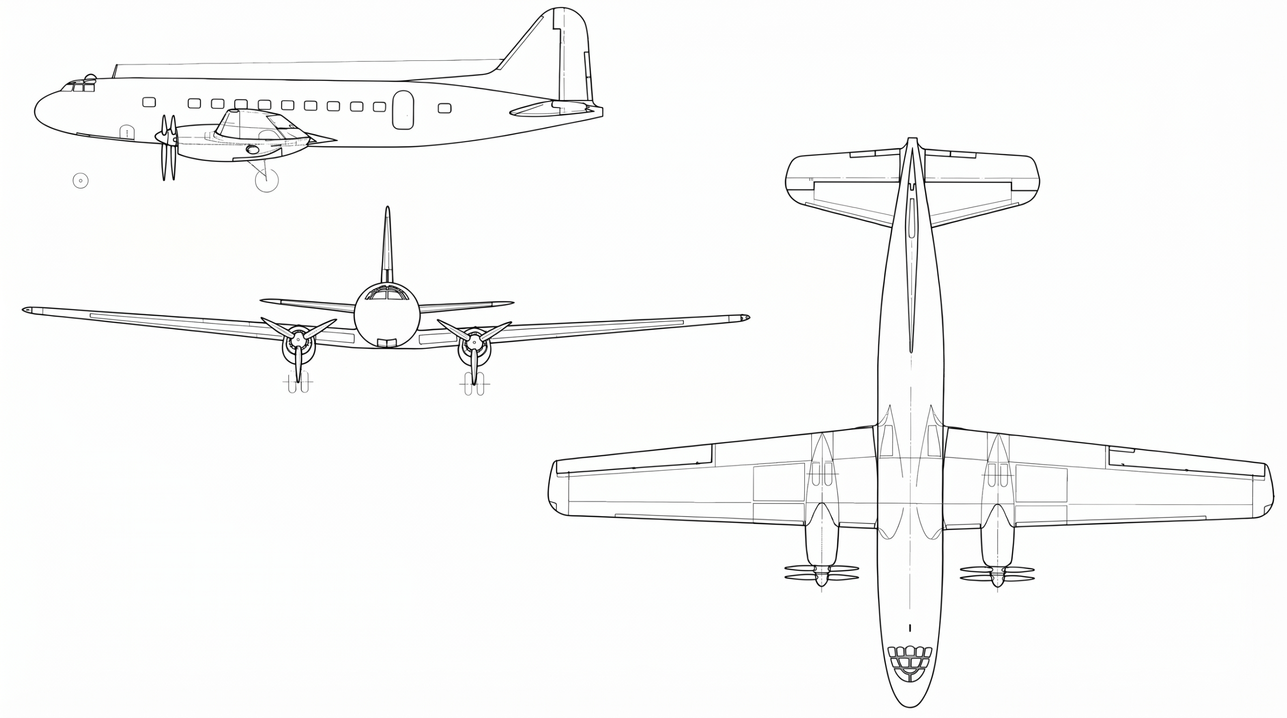
The FC.3 project, or Stage II of development, was essentially the FC.2 project equipped with a pair of Armstrong Siddeley Double Mamba turboprop engines, each of which was equipped with a common gearbox and drove coaxial counter-rotating propellers. Fairey played an important role in the development of the Double Mamba, and this powerplant was widely used in the Fairey Gannet anti-submarine aircraft, which made its first flight in September 1949. The drawing is provided by the author of the article. The image was processed by lmarena.ai
The forward section of the fuselage was to include a streamlined nose with an additional fuselage section inserted between the cockpit and the “blanked-off” fuselage section. The rear row of seats was to be removed, and the rear bulkhead of the passenger cabin was to be moved forward to reduce the interior space.
The Double Mamba consisted of two Armstrong Siddeley Mamba turboprop engines, mounted side by side and equipped with a common gearbox that included two sets of gears to drive, via automatic and hydraulic clutches, coaxial counter-rotating propellers. It was intended that, after takeoff and reaching cruising altitude, half of each engine could be shut down to conserve fuel.
In July 1947, a joint document from the British Ministries of Civil Aviation and Supply, containing specifications for a new passenger aircraft, was submitted to the Committee of the International Civil Aviation Organization (ICAO). When BOAC assumed responsibility for all international routes to and from the United Kingdom (with the exception of Europe and South America), all designs for large medium- and long-range airliners were adapted to meet the requirements of the national carrier. The Brabazon Committee developed specifications for many future design requirements for prospective aircraft, and it was noted that there were a number of gaps in this framework and that further development would be required. This provided Fairey with an opportunity to present its designs
“An Empire aircraft with a medium range”
in response to the requirements of Specification 2/47.
However, this was not to be. The specifications outlined the requirements for a four-engine airliner capable of carrying 42 passengers at a cruising speed of approximately 300–350 miles per hour (485–565 km/h), a payload of 13,300 pounds (6,030 kg), and a range of 1,890 miles (3,040 km). The powerplant options included the Rolls-Royce Clyde, the Bristol Proteus, and the Armstrong Siddeley Python—all turboprop engines developed for military aircraft projects. These competitions were intended to serve as a fallback in case of the possible failure of the de Havilland Comet jet and as a potential replacement for the Brabazon III project, which called for the development of a four-engine, land-based passenger aircraft for the Empire’s main routes (the Type IIIA specification called for an aircraft for North Atlantic routes; the Type IIIB specification called for a medium-range aircraft).
On July 14, 1947, a joint committee consisting of representatives from the Ministries of Supply and Civil Aviation and the airline BOAC announced that the Bristol 175 project (later named the Britannia) was the best design meeting Specification 2/47, while the designs submitted by Armstrong Whitworth, Avro, Blackburn, and Handley Page were rejected. Fairey’s airliner design was not even considered.
The following year, Fairey responded to Specification 5/48, which required
“a civilian airliner for the Empire’s long-haul routes and for North Atlantic routes”
submitted a brochure to the Ministry of Aviation. Proposals were submitted by six companies, including Fairey, which proposed three similar four-engine variants: the FC.4, FC.5, and FC.6—all with mid-wing configurations. The airframe was to be semi-monocoque to combine simplicity of construction with sufficient strength and rigidity. The four engines were to be interchangeable and housed in standardized, removable, streamlined engine nacelles, mounted on the wing’s power-set members via quick-release couplings on their rear bulkheads. Air intakes on the leading edge of the wing were to supply air to specially designed pressure chambers located around the compressor inlet of each engine. The extension tubes of the turboprop engines were to pass through the main spar and terminate in a nozzle immediately behind the trailing edge of the wing.
The wing’s structural assembly, based on a single spar, was supplemented by a rear thin-walled spar to complete the torsional path and compensate for the load moments generated by drag. Each of the main landing gear struts was to consist of two shock-absorbing struts mounted side by side and equipped with single wheels. These shock-absorbing struts pivoted on the wing structure outward in such a way that one support retracted inward toward the fuselage, while the other support retracted toward the wing tip; this allowed the struts and wheels to be fully stowed in recesses within the wing spars. The main landing gear was designed for a vertical descent rate of 14 feet per second (4.2 m/s). The ailerons, elevator, and rudder were equipped with a hydraulically powered control booster system.
The aircraft was to have a double-deck fuselage with a cross-section shaped like two intersecting circles, 12 feet 5 inches (3.7 m) wide and 15 feet 3 inches (4.5 m) high. The plan was to equip the aircraft with a Normalair pressurization system capable of maintaining sea-level cabin pressure up to an altitude of 15,500 feet (4,700 m), after which the cabin pressure would gradually adjust until reaching an altitude of 30,000 feet (9,100 m), at which point the cabin pressure would be maintained at the level of normal atmospheric pressure at an altitude of 8,000 feet (2,400 m). The main differences between the three types lay in their wingspan, fuselage length, and the type of engines in their powerplants.
The Appearance of the Fairey Queen
The aircraft, which was to be named the Fairey Queen, was developed in several variants, including:
-
-
- FC.4 – equipped with Bristol Proteus turboprop engines, a “Super Luxury Aircraft” designed to carry 30–56 passengers;
- FC.5 – was intended to be similar to the FC.4, but with Napier Nomad turbo-diesel composite engines;
- FC.6 – equipped with Bristol Proteus turboprop engines, a “Standard Luxury Aircraft” designed to carry 30–58 passengers.
-
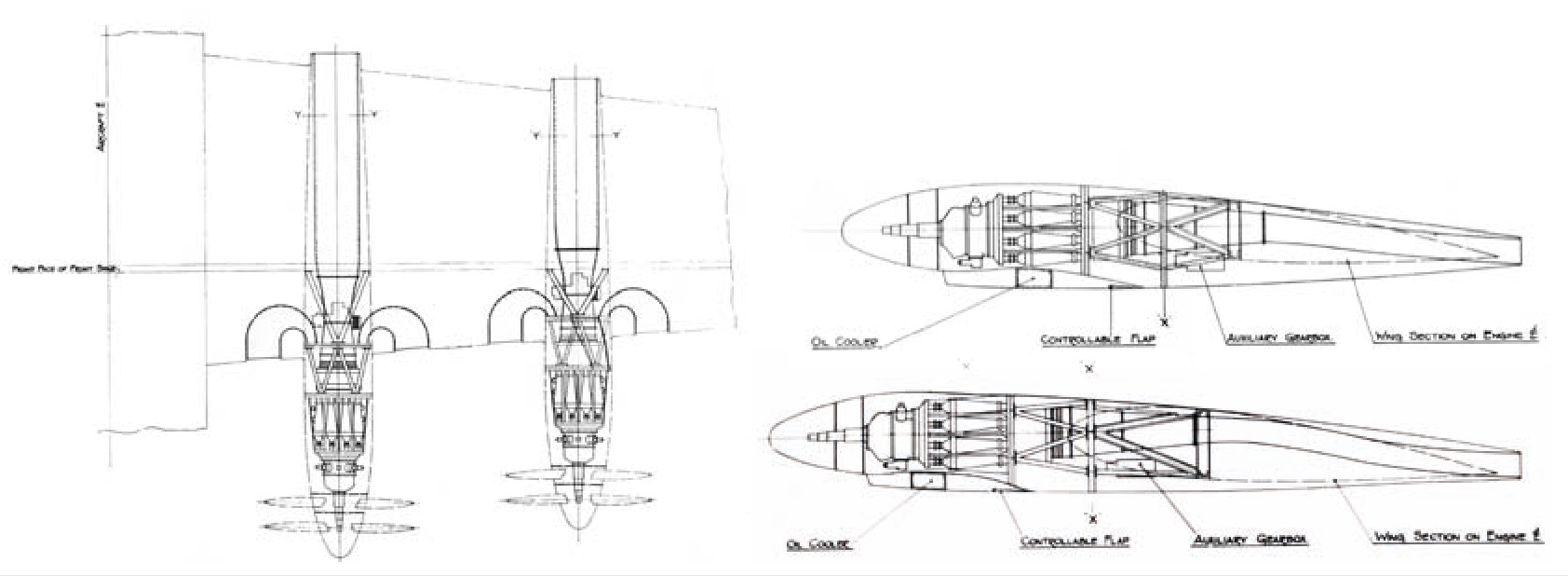
Official illustrations from Fairey showing the gondola layout of the Fairey Queen passenger aircraft project, including a top view of the left wing spar (left). On the right are cross-sections of the outer nacelle (top) and the inner nacelle (bottom). The drawing is provided by the author of the article. The image was processed by lmarena.ai.
Each of these aircraft types could be converted for night flights and equipped with sleeping berths; the letter D or N was added to the designation to indicate a day or night configuration. Alternative sleeping arrangements were proposed: one for 21 passengers in separate, self-contained cabins, and another for 24 passengers in fold-out lounge chairs.
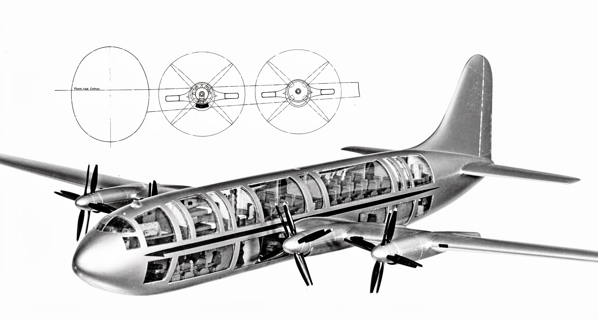
the Fairey Queen passenger aircraft project (designs FC.4 through FC.6 were known by this designation), a precursor to the 21st-century Airbus A380 double-deck airliner, was designed to accommodate up to 58 passengers in a double-deck fuselage with a cross-section shaped like two intersecting circles. The engines were to be housed in aerodynamically clean nacelles, as shown in the front view at the top. The photograph and drawing of the FC.4 design are provided by the author of this article. The image was processed by the website lmarena.ai
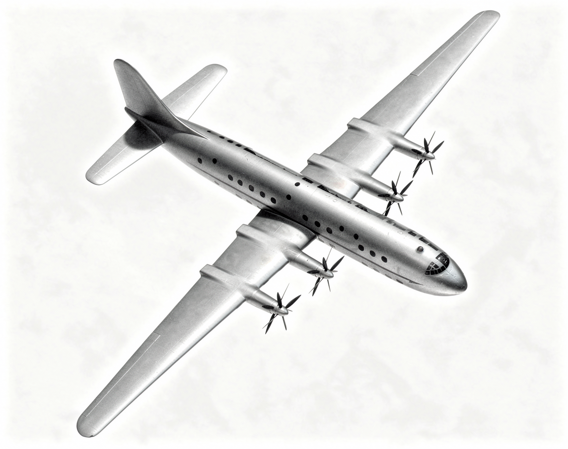
Another photograph of the Fairey Queen passenger aircraft model, showcasing its clean lines and high-aspect-ratio wing. During development, various powerplant options were considered, the main ones being the Bristol Proteus turboprop engines, which powered the Bristol Britannia passenger aircraft, the giant flying boat Saro Princess, and Napier Nomad compound turbodiesel engines. The engines were intended to drive coaxial counter-rotating propellers. The photo was provided by the author of the article. The image was processed by lmarena.ai
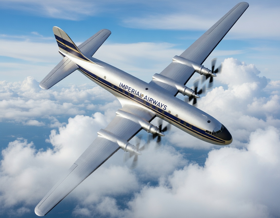
This is what a Fairey Queen passenger plane might have looked like when it entered service. The image was generated by lmarena.ai.
Fairey planned for these aircraft to have a crew of 11, or 13 on particularly long-haul routes. The standard crew consisted of a captain, a first officer, a radio operator, a navigator, a flight engineer, two male flight attendants, and one female flight attendant; the rest of the crew were in the crew lounge. The crew entrance was to be built into the forward cargo door on the starboard side, and the upper deck could be accessed via a staircase leading directly into the cockpit.
In an effort to create the most attractive design in terms of passenger seating for long-haul routes to Australia and South Africa, Fairey developed the following options:
-
-
- a low-wing aircraft with a single-deck fuselage 13 feet (4 m) in diameter;
- the same variant with a single-deck fuselage 11 feet (3.35 m) in diameter;
- a mid-wing aircraft with a two-deck fuselage configuration;
- the same variant with very spacious passenger accommodations.
-
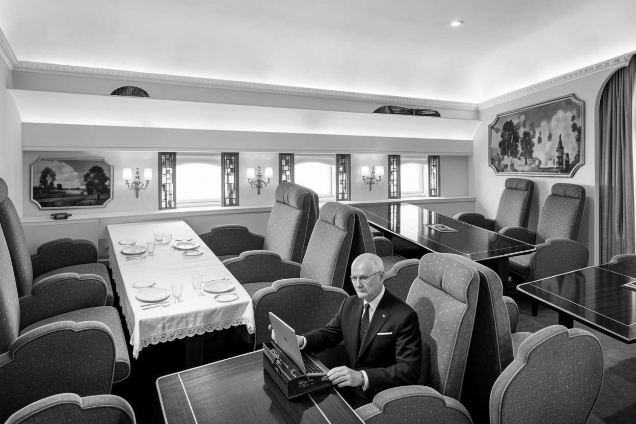
This and the following illustrations from the Fairey brochure present a somewhat utopian vision of the future of air travel aboard the Fairey Queen airliner. This illustration shows the dining room on the lower deck. The illustration is provided by the author of this article. The image was processed by lmarena.ai
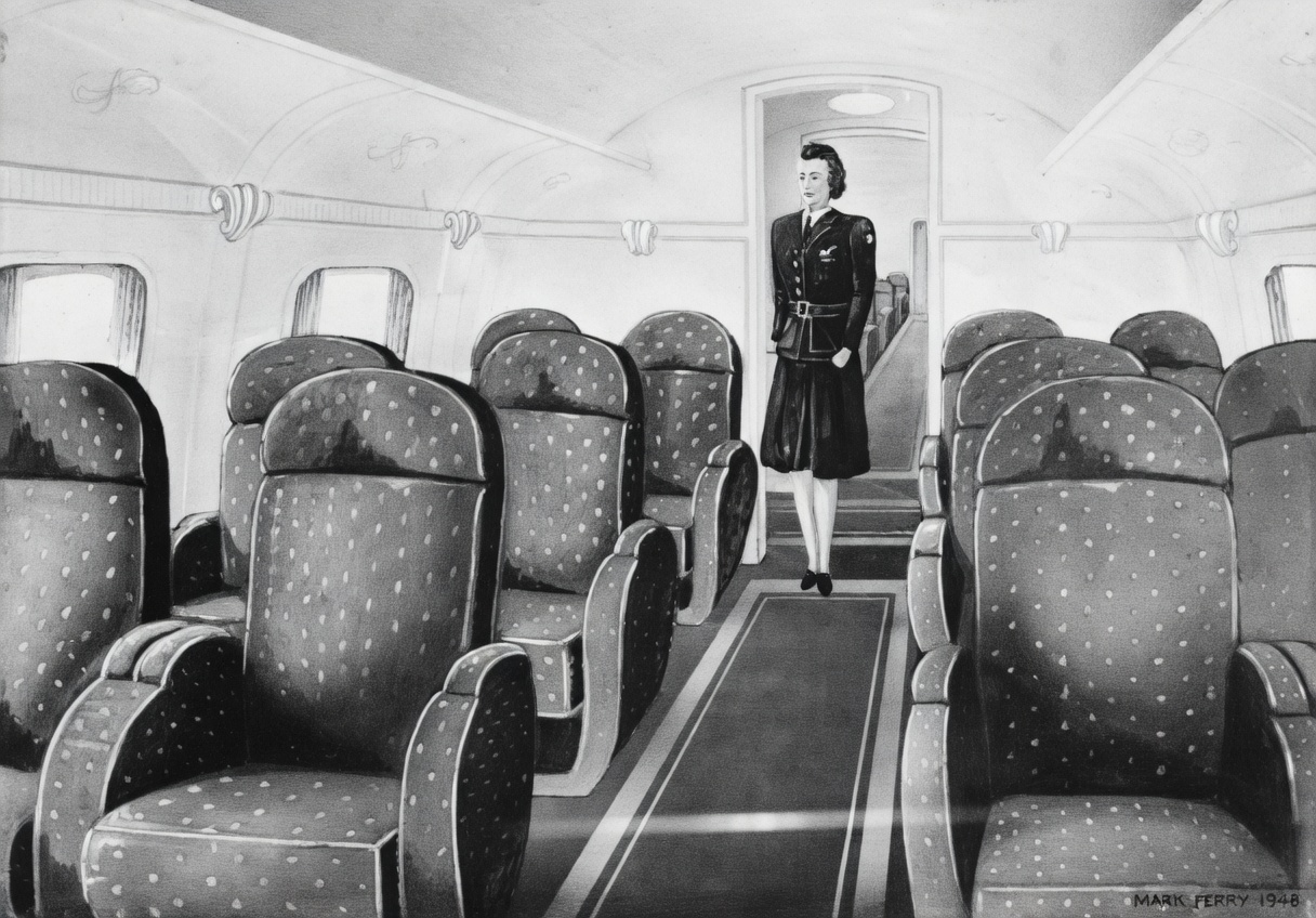
The flight attendant seems out of place in the main passenger cabin on the upper deck; the potential customer was likely hoping for much better results than what is shown in the promotional materials. The image is provided by the author of the article. The image was processed by lmarena.ai
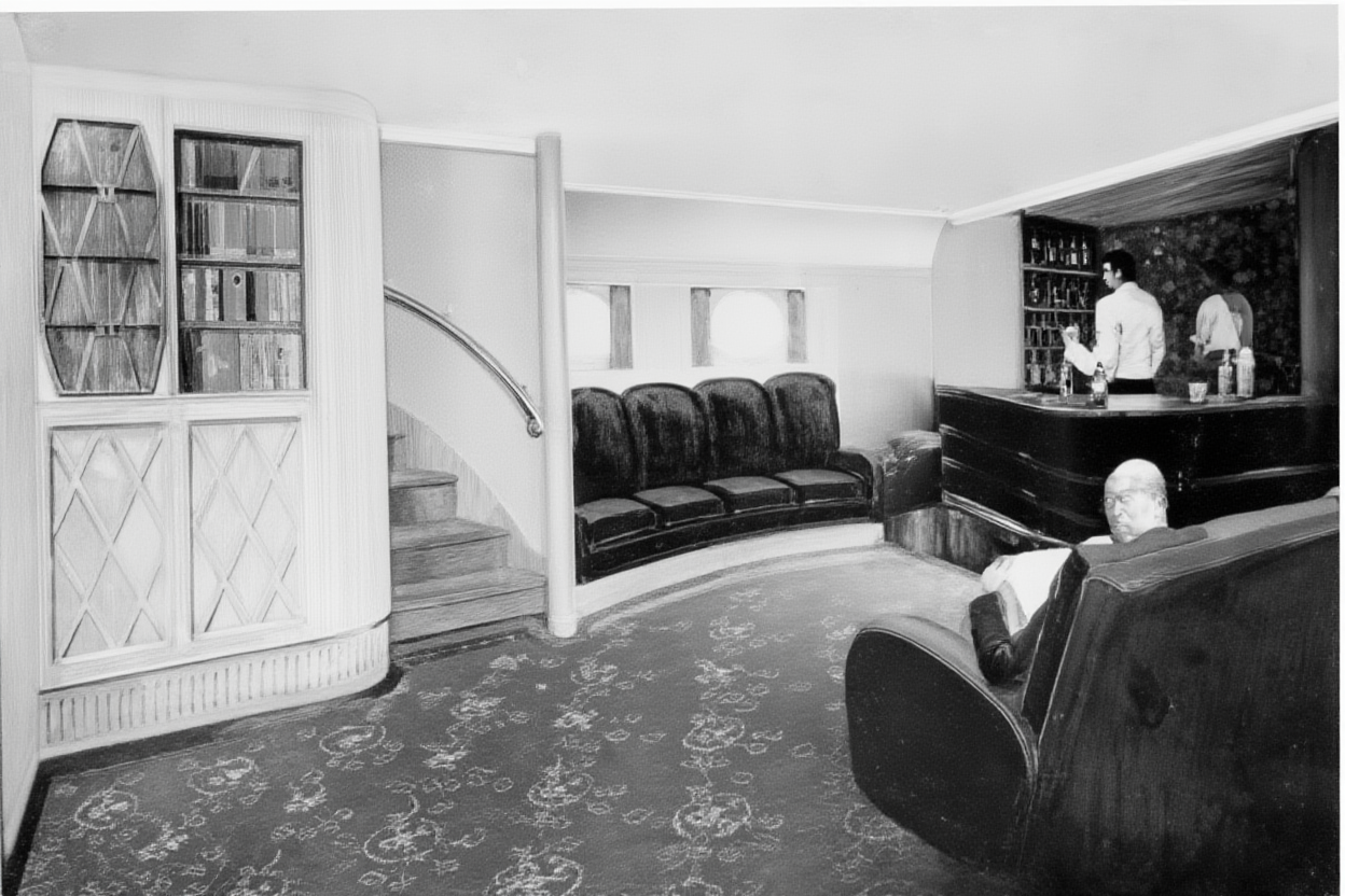
After enjoying an exquisite dinner served on porcelain plates with silver cutlery, passengers aboard the Fairey Queen can retire to the lounge-library, which features a well-stocked bar, a bookcase, and comfortable armchairs. If the Fairey Queen airliner had been built, it would most likely have had an economy-class cabin with a high passenger density. The illustration is provided by the author of the article. The image was processed by lmarena.ai.
Fairey concluded that twin-deck fuselage configurations with a mid-mounted trapezoidal wing featuring a high aspect ratio would be more desirable, and used this configuration as the basis for further research. A unique feature of the fuselage, with a cross-section shaped like two intersecting circles, was a ready-made and accessible external channel running along each side of the fuselage, well-suited for housing control elements, cables, the air conditioning system, and other equipment. All of this equipment could be easily installed and maintained from the outside of the fuselage, leaving its interior space free for necessary internal communications. Quick-release panels facilitated access.
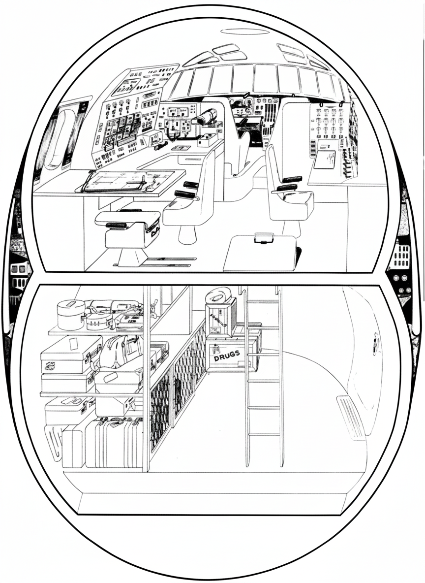
An illustration by Fairey showing a cross-section of the nose section of the Fairey Queen airliner’s double-deck fuselage, featuring a spacious cargo compartment beneath the cockpit. Note the equipment channels running through the voids between the curved upper and lower fuselage sections, which facilitate maintenance. The drawing is provided by the author of the article. The image was processed by lmarena.ai
Not the right time
None of these highly efficient—at least on paper—airliners attracted any buyers, and Fairey’s attempt to break into the passenger aircraft market failed once again. The Brabazon Committee pointed out that new models developed in accordance with the five basic specifications would become obsolete rather quickly, since at that time, innovations were being introduced one after another in the design of aircraft airframes and engines. This was a major reason why the Fairey Queen airliner project lost its relevance. By the time Fairey had brought the development of its airliner to a level that would allow airlines to begin regular operations with it, it would already have been practically obsolete and would have been supplanted by the advent of jet engines. Development of the FC.1 was halted with the outbreak of war, and the number of aircraft the airline was prepared to purchase was too small to justify continuing the project.
By 1947, the FC.2 and FC.3 designs had gone beyond the specifications set by the Brabazon Committee, as had the improved design for the Fairey Queen airliner. However, all was not lost, as Fairey continued to develop a number of important military and experimental aircraft right up until its merger with Westland in 1960, including the Gannet anti-submarine aircraft and the FD.2 supersonic experimental aircraft.
FLIGHT AND TECHNICAL SPECIFICATIONS
| Type: | FC.1 | Federal Circle 2 | First Class |
| Dimensions: | |||
| wingspan | 105 feet 0 inches (32.0 m) | 103 feet 0 inches (31.4 m) | 103 feet 0 inches (31.4 m) |
| length | 76 feet 0 inches (23.2 m) | 80 feet 8 inches (26.5 m) | 80 feet 4 inches (26.0 m) |
| height | 22 feet 6 inches (6.9 m) | 26 feet (7.9 m) | 26 feet (7.9 m) |
| Passengers | 10-30 | 24-30 | 24-30 |
| Weight: | |||
| an empty plane | 28,000 pounds (12,700 kg) | 27,755 pounds (12,589 kg) | 25,240 pounds (11,448 kg) |
| maximum | 45,232 pounds (20,516 kg) | 41,000 pounds (18,597 kg) | 40,630 pounds (18,429 kg) |
| Flight characteristics: | |||
| cruising speed at an altitude of 10,000 feet (3,000 m) | 275 miles per hour (443 km/h) | 275 miles per hour (443 km/h) | 300 miles per hour (483 km/h) |
| Time to climb to 10,000 feet (3,000 m) | 8 min 50 sec | 8 min | 6 minutes 30 seconds |
| practical ceiling | 25,000 feet (7,250 m) | 30,000 feet (9,100 m) | 40,000 feet (12,200 m) |
| range at an altitude of 10,000 feet (3,000 m) | 1,850 miles (2,980 km) | 1,650 miles (2,650 km) | 1,540 miles (2,480 km) |
.
| Type: | First Class 4 | First Class Five | Federal Communications Commission |
| Dimensions: | |||
| wingspan | 163 feet 0 inches (49.7 m) | 163 feet 0 inches (49.7 m) | 158 feet 6 inches (48.1 m) |
| length | 118 feet 0 inches (36.0 m) | 114 feet 0 inches (34.7 m) | 99 feet 9 inches (30.2 m) |
| height | 34 feet 8 inches (10.4 m) | 34 feet 8 inches (10.4 m) | 34 feet 8 inches (10.4 m) |
| Passengers | 30-56 | 30-50 | 30-58 |
| Weight: | |||
| an empty plane | 67,560 pounds (30,644 kg) | 70,060 pounds (31,778 kg) | 61,800 pounds (28,800 kg) |
| maximum | 130,000 pounds (58,967 kg) | 121,000 pounds (54,884 kg) | 121,000 pounds (54,884 kg) |
| Flight characteristics: | |||
| cruising speed at an altitude of 10,000 feet (3,000 m) | 308 miles per hour (496 km/h) | 245 miles per hour (394 km/h) | 300 miles per hour (483 km/h) |
| Time to climb to 10,000 feet (3,000 m) | 7 min | 10 minutes 7 seconds | 8 min |
| practical ceiling | 32,900 feet (10,000 m) | 30,000 feet (9,100 m) | 32,500 feet (9,900 m) |
| range at an altitude of 10,000 feet (3,000 m) | 4,500 miles (7,240 km) | 4,500 miles (7,240 km) | 4,500 miles (7,240 km) |
Power plant:
FC.1 – four air-cooled Bristol Taurus 14-cylinder, two-row radial piston engines, each rated at 1,000 l.s.
FC.2 – four liquid-cooled Rolls-Royce Merlin T.24 12-cylinder V-configuration inline engines, each rated at 1,610 l.s.
FC.3 – two Armstrong Siddeley Double Mamba turboprop engines, each with a net power output of 1,310 l.s., driving coaxial counter-rotating propellers
FC.4 – four Bristol Proteus turboprop engines, each with a net power output of 4,023 l.s., driving coaxial counter-rotating propellers
FC.5 – four 12-cylinder, valveless, two-stroke Napier Nomad diesel engines, each rated at 3,135 l.s. Each engine is equipped with a three-stage turbine that drives the crankshaft and an axial compressor.
FC.6 – four Bristol Proteus turboprop engines, each with a net power output of 4,023 l.s., driving coaxial counter-rotating propellers
источник: B.Harrison «Fairey’s commercial break» «The Aviation Historian» Issue No 21, Pages 96-108
Translation first published at – https://vk.com/@710541705-fairey-s-commercial-break-02